N58 Hardware User Guide
Chapter 5 Application Interfaces
Copyright © Neoway Technology Co., Ltd. All rights reserved.
5.3.4 SDIO
Enabling of the power supply
for SD cards
Pull-up power supply for the
SD card SDIO bus
It is forbidden to supply power
to other loads. Leave this pin
floating if it is not used.
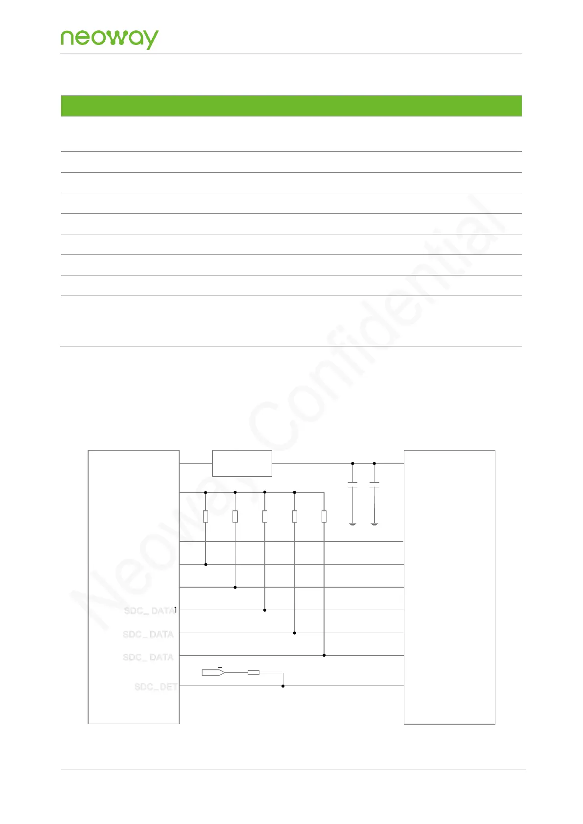
The SDIO interface supports 1.8 V/3.0 V dual-voltage and supports a clock frequency of up to 33.33
MHz. The following figure shows the SDIO reference design.
Figure 5-25 SDIO reference design
SDC
_
CLK
SDC
_
CMD
SDC
_
DATA 0
1
N58 Module
2
3
SD power
suppy
VCC
CLK
CMD
DET
VDD_SDCPULL
_
10
k
Ω
47
k
Ω
VDD
47 k
Ω
47
k
Ω
47
k
Ω
47
k
Ω
SDC_PWR_EN
P1 8
SD Card Slot
4.7uF
33pF
SDC
_
DATA
SDC
_
DATA
SDC
_
DET
SDC
_
DATA
DATA0
DATA1
DATA2
DATA3