N58 Hardware User Guide
Chapter 5 Application Interfaces
Copyright © Neoway Technology Co., Ltd. All rights reserved.
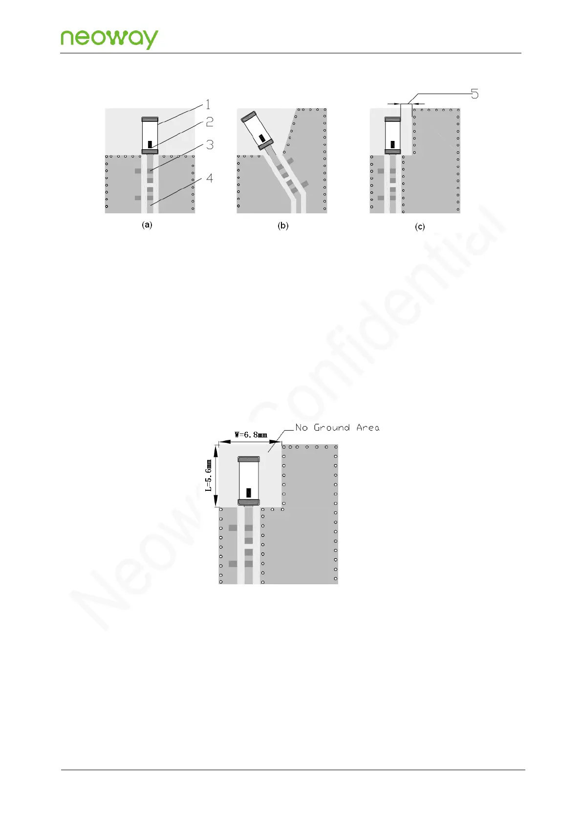
Figure 5-48 Antenna layout example
If the PCB has sufficient space, it is recommended to adopt the layout shown in Figure 5-48 (a).
1: chip antenna
2: mark of the antenna feed end
3: matching circuit pad
4: 50 Ω impedance cable
5 in Figure 5-48 is the area between the antenna and ground. Figure 5-49 shows the layout of this area.
Figure 5-49 Layout around the antenna
For details, refer to antenna manufacturers' usage recommendations and documentation.