N58 Hardware User Guide
Chapter 5 Application Interfaces
Copyright © Neoway Technology Co., Ltd. All rights reserved.
PCB design guidelines:
MIC_P and MIC_N should comply with differential trace rules.
Audio traces must be grounded, and the distance between audio traces and other signal traces
must be greater than or equal to 3 times the cable width.
Place RF filter capacitors close to audio components or audio interfaces.
Keep traces away from noise sources, such as DC-DC power supply.
5.4.2 Analog Audio Output Interfaces
Support for only differential output,
built-in class AB or class D power
amplifier.
Maximum output power:
Class AB: 600 mW@4.2 V, 8 Ω load.
Class D: 800 mW@4.2 V, 8 Ω load.
The recommended reference designs are as follows based on the built-in power amplifier and external
power amplifier of the N58 module.
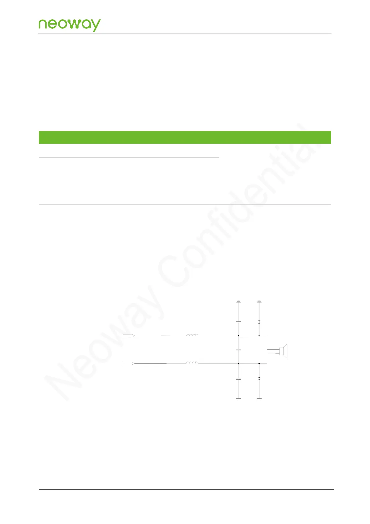
Reference Design of the Built-in Power Amplifier
Figure 5-29 Reference design of the built-in power amplifier
C2
D2
D1
C3
C4
B1
B2
33pF
33pF
33pF
SPK_P
SPK_N
Schematic design guidelines:
C2, C3, and C4 are used to filter out high-frequency interference.
D1 and D2 are TVS diodes used to prevent ESD from damaging the module.
B1 and B2 are ferrite beads used to filter out high-frequency noise. It is recommended to use
ferrite beads specifically for audio.