Model H1301 Recovery and Recycling System
Installation, Operation and Maintenance Manual
Revision-L September, 2019
Page 14 of 105
IV. System Installation (continued)
E. Nitrogen Supply
Clean and dry commercial grade nitrogen gas will be required for system operation.
Evacuate the plumbing to a 2500 micron minimum vacuum level before opening the
nitrogen supply to the machine.
The nitrogen supply must be regulated to no greater than 250 PSIG. Connecting a
supply greater than 250 PSIG to the Nitrogen Supply Port may cause the pressure relief
valve inside the machine to activate.
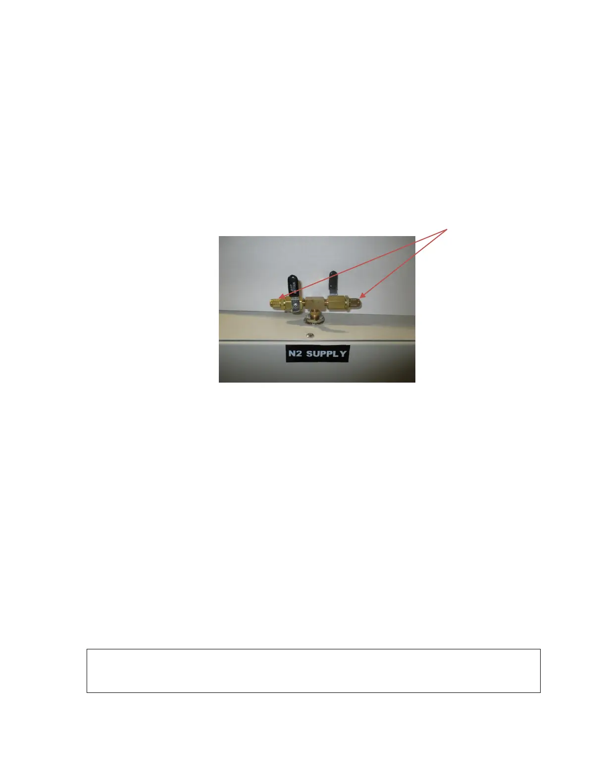
The Nitrogen Supply port and Evacuation Port are located at the top of the machine.
The connections are interchangeable use either valve for nitrogen or evacuation.
Two shut off valves are provided with ¼” x 45° SAE male flare connectors.
Evacuation and Leak Testing Method:
1. Remove the valve caps and set aside.
2. Connect the nitrogen gas source to one of the valves. Do not open the nitrogen
cylinder.
3. Connect a vacuum pump and vacuum gauge to the remaining valve.
4. Open both valves, with the nitrogen source closed, and operate the vacuum pump to
achieve a 2500 micron vacuum level: this will remove air from the interconnecting
plumbing.
5. Close the valve connected to the vacuum pump. Discontinue vacuum pump operation
and disconnect the vacuum pump from the valve. Reconnect the valve cap back to the
valve.
6. Open the nitrogen gas source regulated from 140 to 250 PSI with the valve of the
machine remaining opened.
7. Leak test the plumbing connections using leak detect fluid. If no leakage is detected the
nitrogen installation is complete, or repair any leaks if required, then repeat the evacuation
procedure.
WARNING: DO NOT CONNECT GAS IN EXCESS OF 250 PSIG TO THE
NITROGEN SUPPLY PORT OF THE MACHINE. DAMAGE TO THE
EQUIPMENT MAY RESULT.



 To Next Page