Model H1301 Recovery and Recycling System
Installation, Operation and Maintenance Manual
Revision-L September, 2019
Page 50 of 105
VII. System Maintenance Procedures (continued)
H. Moisture, Acid, and Processed Particulate Filter Element Replacement
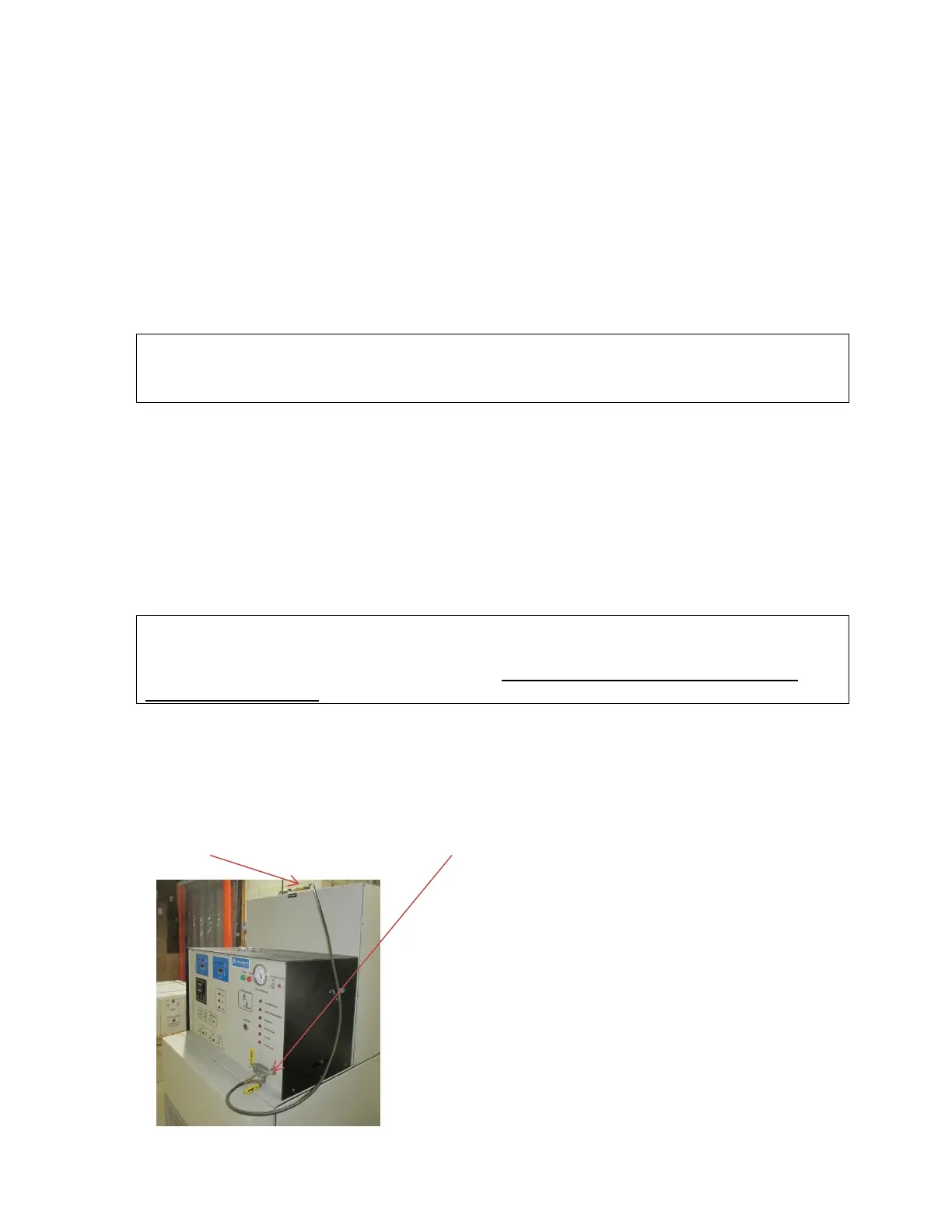
Figures 10 and 11 will detail the location and replacement of the moisture, acid, and
processed particulate filter elements. The moisture and acid filter/drier cores should be
replaced after every 2000 pounds of AGENT processed or whenever the moisture
indicator of the front panel does not indicate a violet color. The processed particulate filter
element should be replaced at yearly intervals due to the low influx of particulate
contamination at this point in the machine. The processed particulate filter element will
require early replacement if the red indicating button of the filter is extended out past the
indicator ring. The moisture and acid filters cores must be replaced if the processed
particulate filter element is serviced.
CAUTION: ALWAYS replace both the moisture and acid filter/drier cores together.
The indication of required maintenance applies to both the moisture and
acid filters.
Replacement Procedure
Required Materials:
Vacuum Pump
Clean Dry Nitrogen Gas
Cloth Rags
Vacuum Gauge
Pressure Gauge
¼” Refrigeration Service Hoses
Straight Blade Screwdriver
½” Socket Torque Wrench 20 to 100 inch pound indicator
Leak Detector Fluid
NOTE: Filter replacement is most easily accomplished just after the machine stops
processing automatically and the empty source container is disconnected. If the source
container is not empty perform section-V.E: Disconnecting the Source Container
When it is not empty; before starting this procedure.
1. Depress and release the Stop Button on the front panel.
2. Verify that the Manual Inlet Valve (MV-1), and the Inlet Evacuation Valve (MV-8) are
closed.
3. Connect nitrogen gas regulated from 140 to 250 psi to the Manual Inlet Valve (MV-1).
The nitrogen supply to the machine can be used in place of a second source of nitrogen
gas. This can be accomplished by connecting the Nitrogen Supply Evacuation Valve
(MV-6) to the Manual Inlet Valve (MV-1) with a refrigeration service hose.