Model H1301 Recovery and Recycling System
Installation, Operation and Maintenance Manual
Revision-L September, 2019
Page 38 of 105
VI. System Operational Description and Component Review
This section of the manual will detail automatic system operations through each of the
internal components of the machine. Refer to the enclosed pneumatic diagram, for
component identification and AGENT flow through the machine.
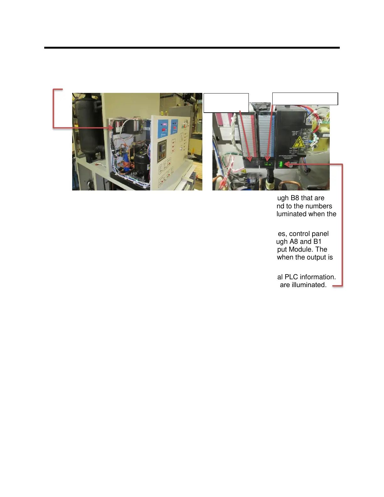
A. PLC unit Status Indicators
The PLC unit coordinates and controls all of the functions of the machine.
The PLC unit has sixteen inputs numbered A1 through A8 and B1 through B8 that are
connected to the various sensors of the machine. The inputs correspond to the numbers
on the of the PLC status display on the Input Module. The number is illuminated when the
corresponding input is activated and off when the input is deactivated.
The PLC unit has sixteen 110 VAC outputs that drive the solenoid valves, control panel
lamps, and pumps of the machine. The outputs are numbered A1 through A8 and B1
through B8 and correspond to the status indicator numbers on the Output Module. The
number is illuminated when the corresponding output is active and off when the output is
deactivated.
The PLC status indicators of the Power Supply Module contains internal PLC information.
The PLC will be operating correctly when the “OK” and “RN” indicators are illuminated.
The PLC unit requires no user adjustments. Below is a listing of the input and output
connections so that a better understanding of the component level operation of the
machine may be gained. The below listing will also aid with trouble shooting in the event
of component failure.
INPUT SOURCE FUNCTION
A1 TEMPERATURE CONTROLLER ALARM #2 Closes OK TO VENT
A2 PRESSURE CONTROLLER ALARM #2 Opens END FINAL VENT
A3 PRESSURE CONTROLLER ALARM #1 Closes END INTERMEDIATE VENT
A4 START SWITCH Closes START AUTO MODE
A5 STOP SWITCH Opens STOP AUTO MODE
A6 VACUUM SWITCH (P2) Opens SOURCE TANK EMPTY
A7 INLET PRESSURE SWITCH (P1) Closes INLET VAPOR RECOVERY
A8 PROCESS LIQUID LEVEL SWITCH (L2) Closes HIGH LIQUID LEVEL
B1 ACCUMULATOR LEVEL SWITCH (L1) Opens SELF EVACUATION MODE
B2 PROCESS LIQUID LEVEL SWITCH (L2) Closes LOW LIQUID LEVEL
B3 PUMP START SWITCH Closes BEGIN PUMP OUT CYCLE
B4 PROCESS LIQUID LEVEL SWITCH (L2) Closes MID LIQUID LEVEL
B5 PROCESS TANK PRESSURE SWITCH (P3) Opens STOP INLET / WAIT TO VENT
B6 NOT USED
B7 COMPRESSOR PRESSURE SWITCH (P5) Opens STOP & INDICATE ERROR
B8 NOT USED