EasyManua.ls Logo

Neutronics H1301 - Page 23

Default Icon
105 pages
Print Icon
To Next Page IconTo Next Page
To Previous Page IconTo Previous Page
Loading...
Model H1301 Recovery and Recycling System
Installation, Operation and Maintenance Manual
Revision-L September, 2019
Page 23 of 105
V. System Operations and Controls
A. Manual Overrides and System Controls (continued)
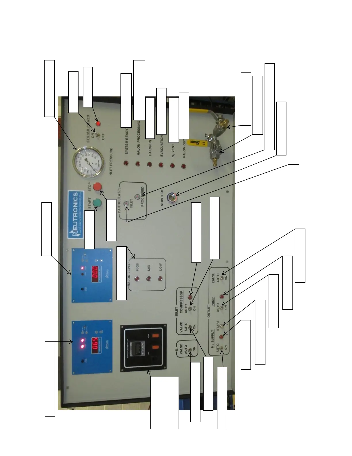
Figure #5: Front Control Panel Detail
1. Power Switch
2. Power Lamp
3. System Ready Lamp
5. Agent In Lamp
6. Evacuation Lamp
7. N2 Vent Lamp
8. Agent Out Lamp
9. Manual Inlet Valve
10. Inlet Evacuation Valve
11. Processed Particulate Filter Indicator
12. Moisture Indicator
13. Inlet Particulate Filter Indicator
26. Pressure Controller
30. Liquid Level Lamps
14. Inlet Compressor Lamp
15. Inlet Compressor Switch
16. Outlet Valve Switch
22. Inlet Valve Switch
17. Outlet Pump Lamp
18. Outlet Pump Switch
19. Outlet Pump Start Switch
23. N2 Vent Valve Switch
20. N2 Supply Lamp
21. N2 Supply Valve Switch
24. Cooling System
Controller
25. Process Temperature Controller
27. Inlet Pressure Gauge
28. Start Button
29. Stop Button

Table of Contents