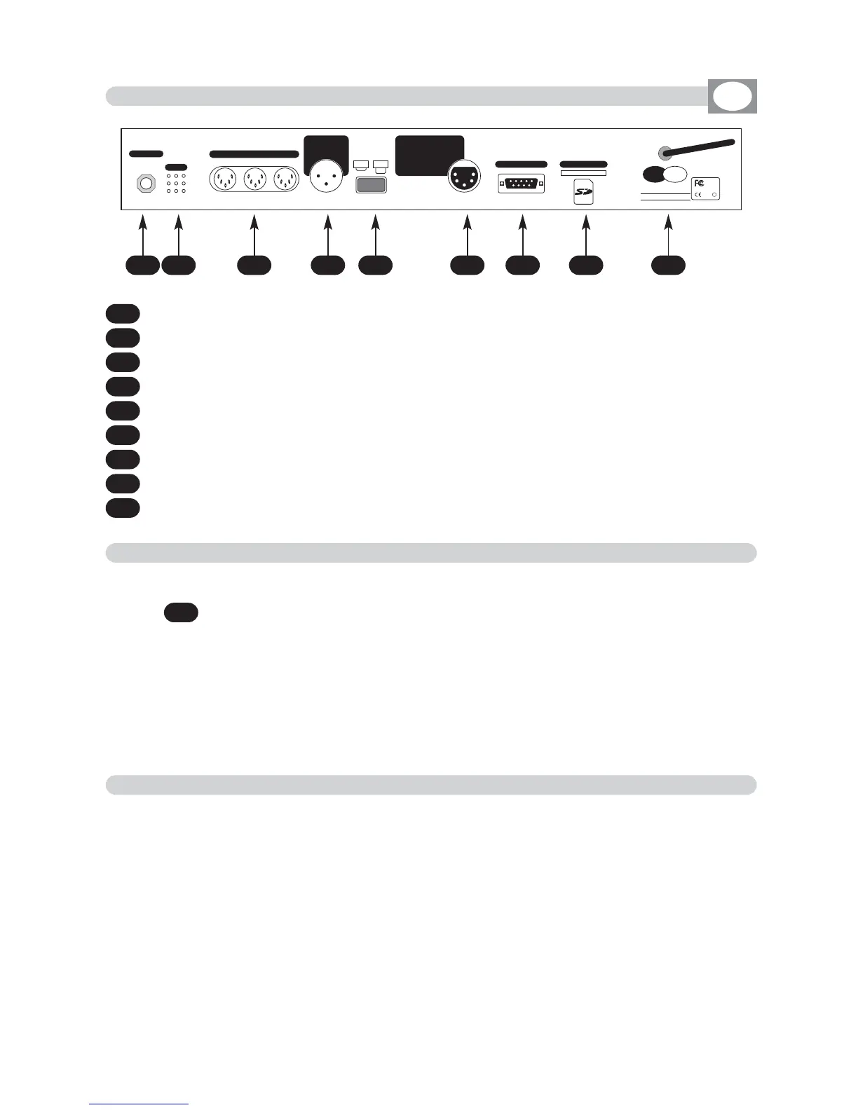
2.1 DESCRIPTION OF THE REAR PANEL
1
0 dB audio signal INPUT with a mono/stereo jack connector.
2
MICROPHONE for the
MMUUSSIICC
function
3
4
MIDI
12 Vac power INPUT with a 3-pin cannon connector.
5
POWER KEY
6
Standard DMX 512 signal INPUT/OUTPUT with a 5-pin cannon connector.
7
RS232 signal INPUT.
8
SD card slot
9
Antenna for built in WI-DMX wireless Transmitter
1 2 43 6 7 8 95
GB
2.2 INPUT CONNECTION FOR POWER SUPPLY
2.3 CONNECTION OF THE AC ADAPTER TO THE MAIN AC
Plug the 3-pin cannon connector of the AC adapter completly in the power
input
Use the “push” safety hook to disconnect it and extract it gently.
ATTENTION: do not use AC adapter different from the one supplied, it could
cause serious damages at the internal circuitation.
Do not connect the 3-pin cannon connector in other appliances, it has been
studied to be used only in this controller.
4
MAKE SURE THAT VOLTAGE AND POWER FREQUENCY CORRESPOND TO
WHAT IS REPORTED ON THE AC ADAPTER PLATE.
Press
POWER
key to verify the correct installation.
If pressing the
POWER
key no leds light up, please check if there is tension in
the electric socket or check the connection between AC adapter-controller and
AC adapter-electric socket.
If the problem persists, please consult your dealer.
®