Installation
18
TemBreak PRO P_BE-UM-001-EN V1.3.0
Insulating Distance
When earth metal is installed within proximity of the breakers, the correct insulating distance must be maintained, (refer to Minimum Clearance).
This distance is necessary to allow the exhausted arc gases to disperse. This could include the mounting plate or side panel within a switchboard.
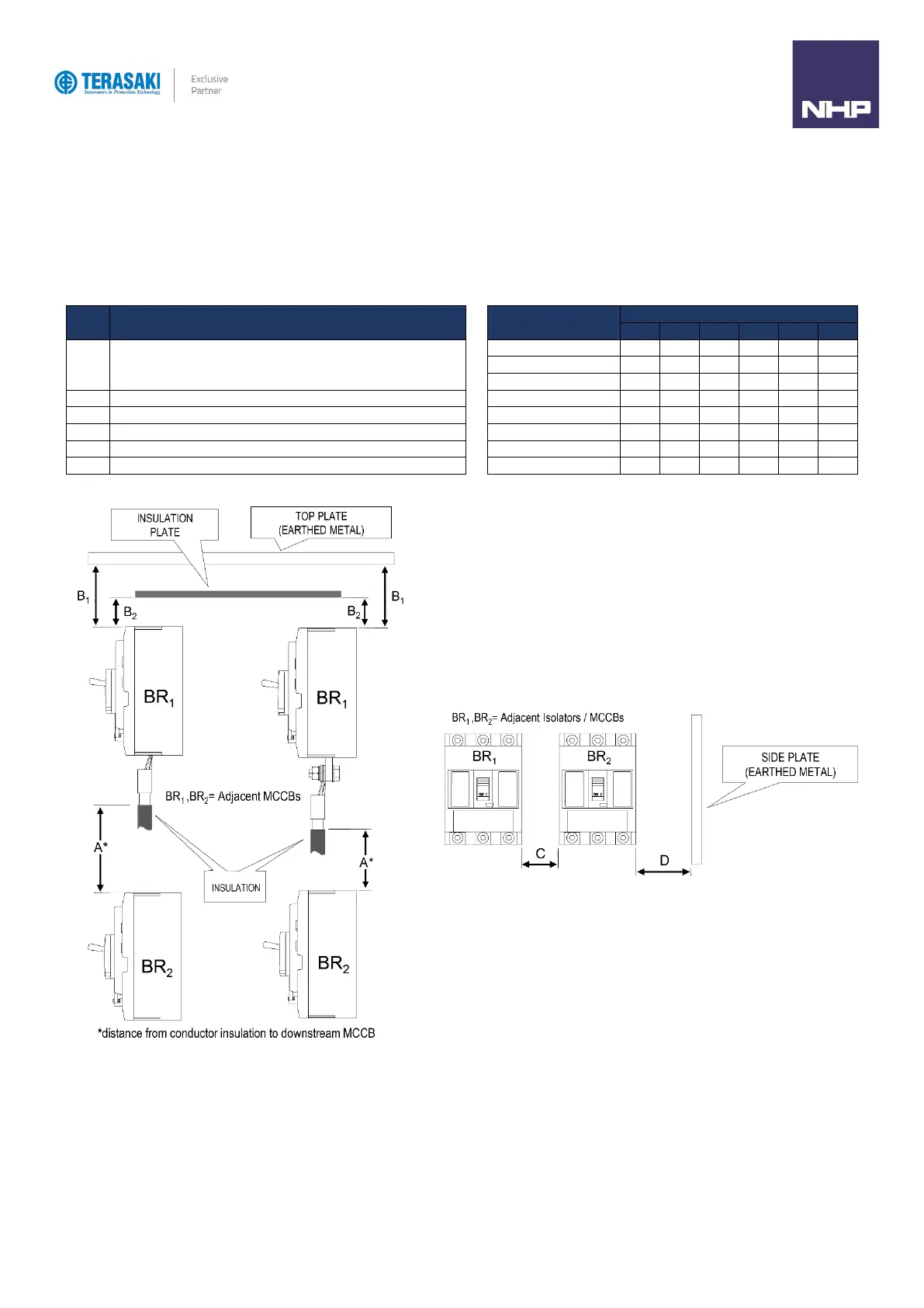
Minimum Clearance
Below illustrates the minimum clearance that must be maintained.
Distance from lower breaker to open charging part of terminal on
upper breaker (front connection) or the distance from lower
breaker to upper breaker end (rear connection and plug-in type)
Distance from breaker end to ceiling (earthed metal)
Distance from breaker end to insulator
Clearance between breakers
Distance from breaker side to side plate (earthed metal)
Length of insulation over exposed conductors.
^ Insulate the exposed conductor until it overlaps the moulded case at the terminal, or the terminal cover.