Alarms & Indication
40
TemBreak PRO P_BE-UM-001-EN V1.3.0
PTA (Pre-Trip Alarm)
The Pre-Trip Alarm permits monitoring and early warning of overload conditions prior to an actual LTD trip. The PTA setting is defined by two parameters
which define the Pre-trip warning and Pre-trip Alarm zones and thus the behaviour of the PTA contact and status LED:
-
PTA current threshold I
p
: Threshold expressed as a percentage of I
r
and is fixed at 80% x I
r
.
-
PTA time delay t
p
: Expressed as a percentage of t
r
and is fixed at 50% x t
r
.
The I
p
current threshold defines the lowest current that could be considered to be within the Pre-trip warning and Pre-trip alarm zones. The t
p
time delay
threshold defines the shortest time in which the Pre-trip alarm will activate. The time delay for PTA follows the LTD protection curve and varies with current
as shown in the figure below. Lower currents in the Pre-trip zones will activate the alarm with a longer delay than higher currents.
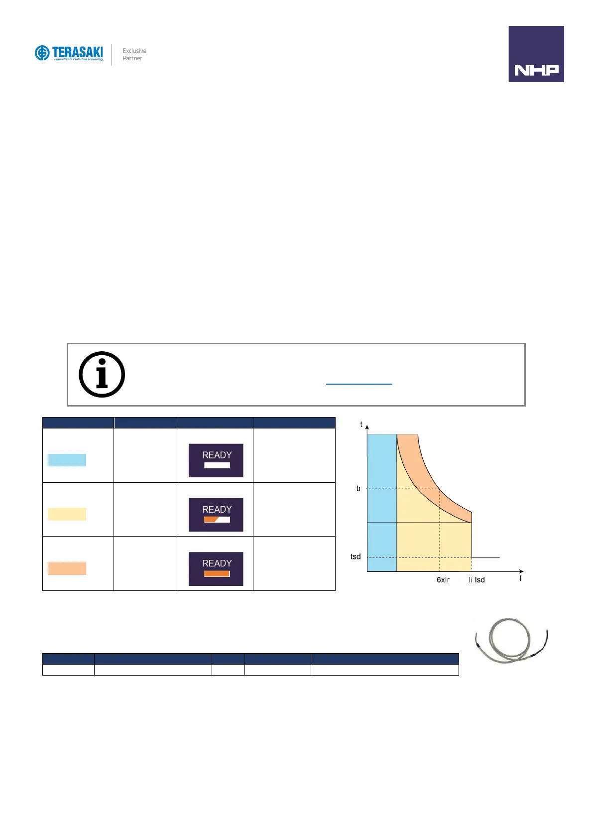
The behaviour of the various pre-trip zones are illustrated in the figure and table below.
If the load current is less than the I
p
current threshold, then this is considered the normal load zone, and the PTA LED and contact are unaffected and
remain OFF and OPEN, respectively.
As the load current increases to at or above I
p
, the Pre-trip warning zone is entered, and is indicated by the PTA LED illuminating FLASHING orange. Whilst
in the pre-trip warning zone, the load current is monitored and characterised with thermal imaging by the OCR.
If the current remains above I
p
for an extended period of time, the Pre-trip Alarm zone is entered, and is indicated by the PTA LED illuminating SOLID
orange, and the PTA contact activating CLOSED. The time required for the Pre-trip Alarm to activate is dependent on the current value and the t
p
parameter
set, as this follows the LTD protection curve.