Protection Settings
37
TemBreak PRO P_BE-UM-001-EN V1.3.0
Neutral Protection (NP)
Neutral protection is available with 4P P_BE MCCBs with LSIG OCR. It is particularly useful when the cross-section of the neutral conductor is reduced in
relation to the phase conductors.
Neutral protection is based off the standard LTD and STD protection parameter of the main phases. The I
r
and I
sd
parameters for the Neutral pole are
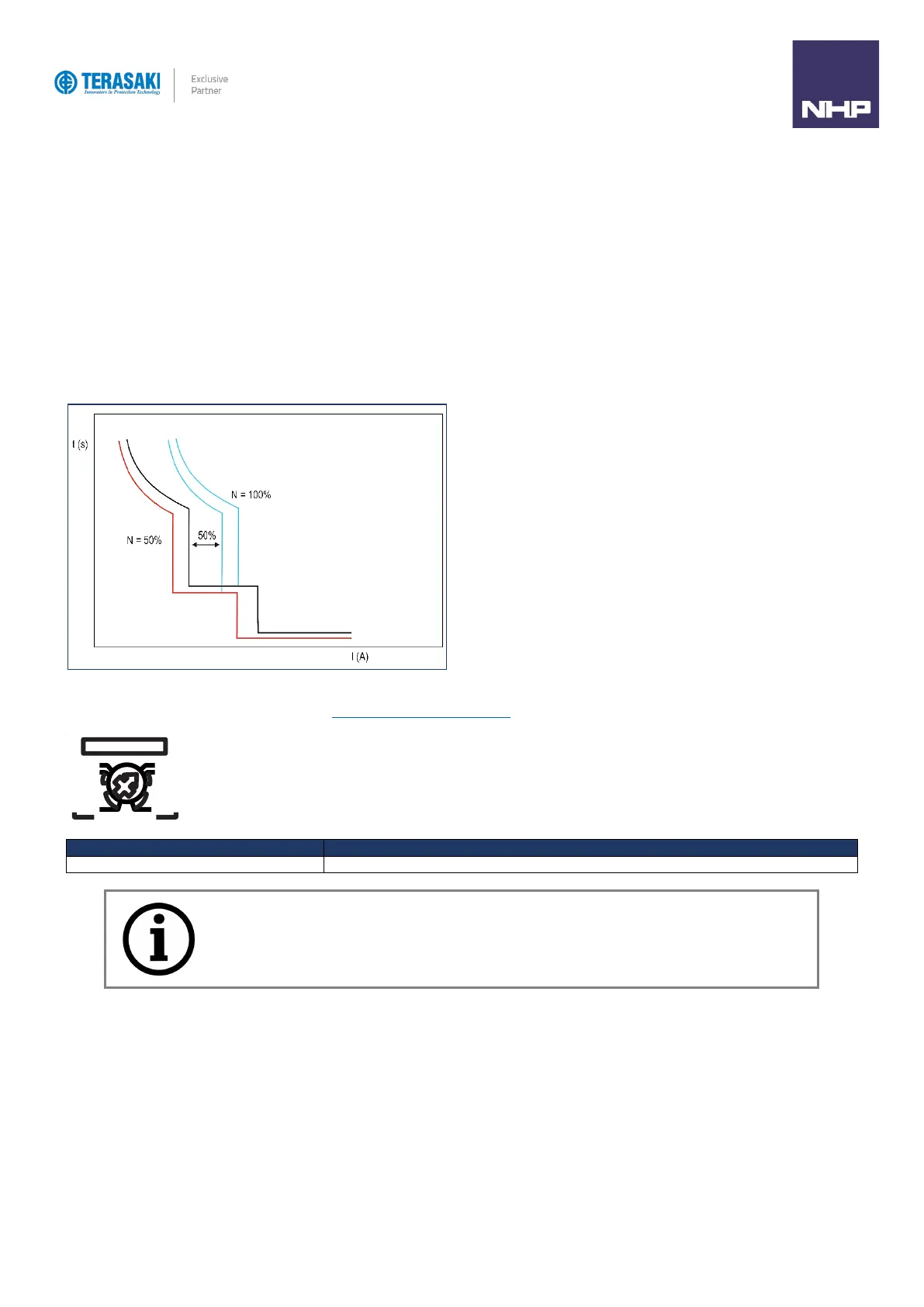
adjusted according to the set Neutral Coefficient percentage. For example, If the Neutral conductor is sized at 50% of the main phases, and the N
Coefficient Adjustment parameter is set to 50%, then I
r
and I
sd
of the Neutral pole will be 50% of I
r
and I
sd
of main phase poles.
The time delays for the Neutral pole remain identical to the t
r
and t
sd
time delay adjustment values for the main phases and cannot be independently
changed.
INST protection of the Neutral pole is not affected by the N Coefficient adjustment setting and is identical to the I
i
trip threshold of the main phases.
The Neutral Coefficient percentage can be adjusted from the N (%) dial. GF protection is also turned ON or OFF by setting the dial to any position on the
right for ON, or any position on the left for OFF. See Ground/Earth Fault Protection (GF) section for more information on the N (%) dial.
Notice: If the I
2
t function for STD is enabled, I
2
t will also be included in the Neutral Protection curve as
calculated from the Neutral pole I
r
parameter.