General
%7
41
%7
(%
8%
40
:3
40
8%
$$
$$;-
%7
8%
40
$$;-
6)
40
;/
;/ ;/
;/ ;/ ;/
)5
3)
3)
3)
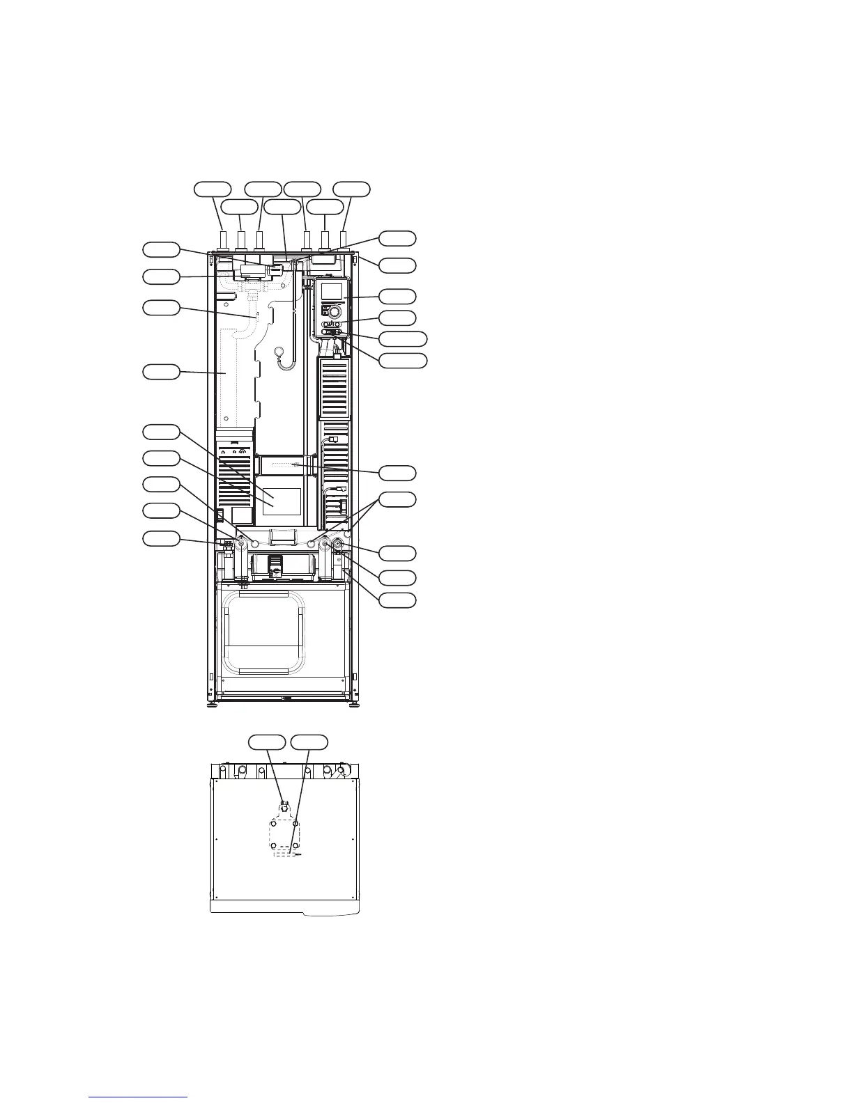
View from above
;/ %7
Pipe connections
Connection, heating medium flowXL 1
Connection, heating medium returnXL 2
Connection, cold waterXL 3
Connection, hot waterXL 4
Connection, VVC*XL 5
Connection, brine inXL 6
Connection, brine outXL 7
* Only applies to enamelled or stainless steel vessels.
HVAC components
Venting, coilQM 22
Shut off valve, heating medium returnQM 32
Shut off valve, brine outQM 33
Shut-off valve, brine inQM 34
Shuttle valve, climate system/water heaterQN 10
Pipe connection, heating medium flowWP 4
Sensors etc.
Outside sensorBT 1
Temperature sensors, heating medium flowBT 2
Temperature sensor, hot water chargingBT 6
Temperature sensor, hot water topBT 7
Electrical components
Display unitAA 4
AA4-XJ3 USB outlet (no function)
AA4-XJ4 Service outlet (No function)
Immersion heaterEB 1
Sacrificial anode*FR 1
SwitchSF 1
* Only heat pump with enamelled vessel.
Miscellaneous
Rating platePF 1
Type plate, cooling sectionPF 2
Serial number platePF 3
Cable gland, incoming electricityUB 1
Cable glandUB 2
Cable gland, rear side, sensorUB 3
Designations in component locations according to
standard IEC 81346-1 and 81346-2.
NIBE™ F1245Chapter 3 | The heat pump design8
3 The heat pump design

 Loading...


