Room sensor
F1245 is delivered with a room sensor supplied (BT50).
The room temperature sensor has up to three functions:
1.
Show current room temperature in the heat pump's
display.
2.
Option of changing the room temperature in °C.
3.
Makes it possible to change/stabilise the room tem-
perature.
Install the sensor in a neutral position where the set
temperature is required. A suitable location is on a free
inner wall in a hall approx. 1.5 m above the floor. It is
important that the sensor is not obstructed from measur-
ing the correct room temperature by being located, for
example, in a recess, between shelves, behind a curtain,
above or close to a heat source, in a draft from an extern-
al door or in direct sunlight. Closed radiator thermostats
can also cause problems.
The heat pump operates without the sensor, but if one
wishes to read off the accommodation's indoor temper-
ature in F1245’s display the sensor must be installed.
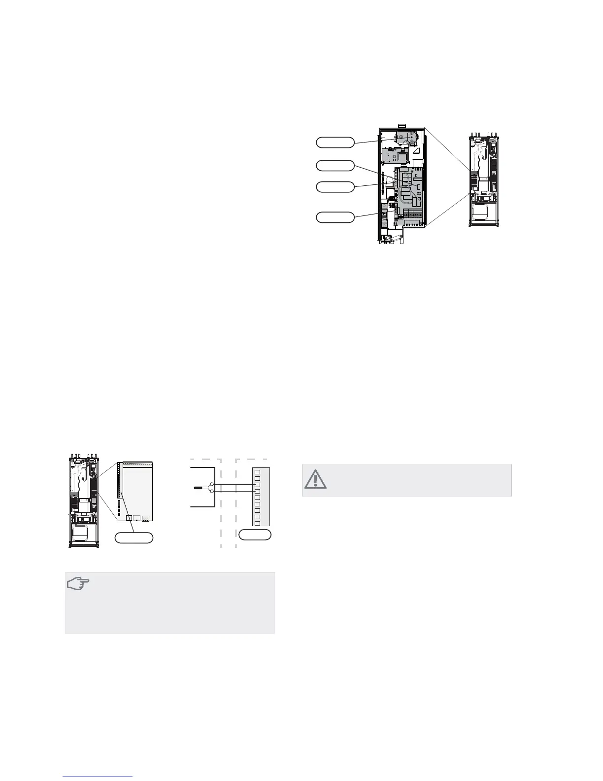
Connect the room sensor to X6:3 and X6:4 on the input
circuit board (AA3).
If the sensor is to be used to change the room temperat-
ure in °C and/or to change/stabilise the room temperat-
ure, the sensor must be activated in menu 1.9.4.
If the room sensor is used in a room with under floor
heating it should only have an indicatory function, not
control of the room temperature.
1
2
3
4
5
6
7
8
9
F1245RG 05
$$;
)5RRP VHQVRU
$$;
Caution
Changes of temperature in accommodation take
time. For example, short time periods in combin-
ation with underfloor heating will not give a
noticeable difference in room temperature.
Settings
$$;
$$;
$$6)
)'%7
Electrical addition - maximum output
On delivery, the immersion heater is connected for a
maximum of 7 kW (3x400V and 1x230V) or 9 kW
(3x230V). For 3x400V the immersion heater cannot be
switched to 9 kW.
The immersion heater's output is split into seven steps
(four steps at 3x230V or if the immersion heater for
3x400V is switched to maximum 9 kW), according to the
table below.
Setting max electrical output
Setting maximum output in the electrical addition is done
in menu 5.1.12.
The tables display the total phase current for the immer-
sion heater.
Switching to maximum electrical output
NOTE
This switch only applies to 3x400V.
If more than the maximum output for the immersion
heater connected on delivery is needed, the heat pump
can be switched to maximum 9 kW.
Move the white cable from terminal block X7:23 to ter-
minal block X3:13 (the seal on the terminal block must
be broken) on the immersion heater card (AA1).
21Chapter 5 | Electrical connectionsNIBE™ F1245

 Loading...


