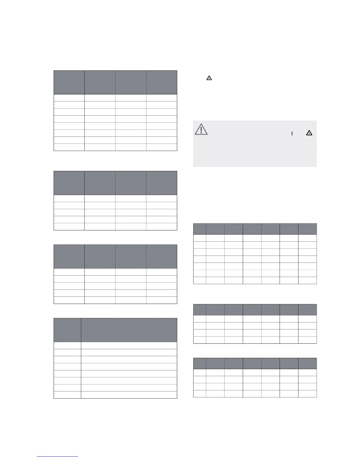
3x400V (maximum electrical output, connected
upon delivery 7 kW)
Max phase
current
L3(A)
Max phase
current
L2(A)
Max phase
current
L1(A)
Max elec-
trical addi-
tion (kW)
0000
4.3001
08.702
4.38.703
8.78.704
4.38.78.75
8.78.78.76
138.78.77
3x400V (maximum electrical output, switched to
9 kW)
Max phase
current
L3(A)
Max phase
current
L2(A)
Max phase
current
L1(A)
Max elec-
trical addi-
tion (kW)
0000
08.702
8.78.704
8.78.78.76
16.216.28.79
3x230V
Max phase
current
L3(A)
Max phase
current
L2(A)
Max phase
current
L1(A)
Max elec-
trical addi-
tion (kW)
0000
09.49.42
8.715.69.54
15.615.615.66
25.627.415.69
1x230V
Max phase current L1(A)Max elec-
trical addi-
tion (kW)
00
4.31
8.72
133
17.44
21.75
26.16
30.47
If the current sensors are connected, the heat pump
monitors the phase currents and allocates the electrical
steps automatically to the least loaded phase.
Emergency mode
When the heat pump is set to emergency mode (SF1 is
set to
) only the most necessary functions are activated.
႑
The compressor is off and heating is managed by the
immersion heater.
႑
Hot water is not produced.
႑
The load monitor is not connected.
NOTE
Switch (SF1) must not be moved to " "or" "
until F1245 has been filled with water. Other-
wise the temperature limiter, thermostat, com-
pressor and the immersion heater can be dam-
aged.
Power in emergency mode
The immersion heater’s output in emergency mode is set
with the dipswitch (S2) on the immersion heater circuit
board (AA1) according to the table below. Factory setting
is 6 kW.
3x400V (maximum electrical output, connected
upon delivery 7 kW)
654321
onoffoffoffoffoff1kW
offoffoffonoffoff2kW
onoffoffonoffoff3kW
offonoffonoffoff4kW
onoffoffonoffon5kW
offonoffonoffon6kW
ononoffonoffon7kW
3x400V (maximum electrical output, switched to
9 kW)
654321
offonoffoffoffoff2kW
offonoffonoffoff4kW
offonoffonoffon6kW
ononononoffon9kW
3x230V
654321
offoffonoffoffoff2kW
offoffononoffoff4kW
offoffonoffonon6kW
offoffonononon9kW
NIBE™ F1245Chapter 5 | Electrical connections22

 Loading...


