1x230V
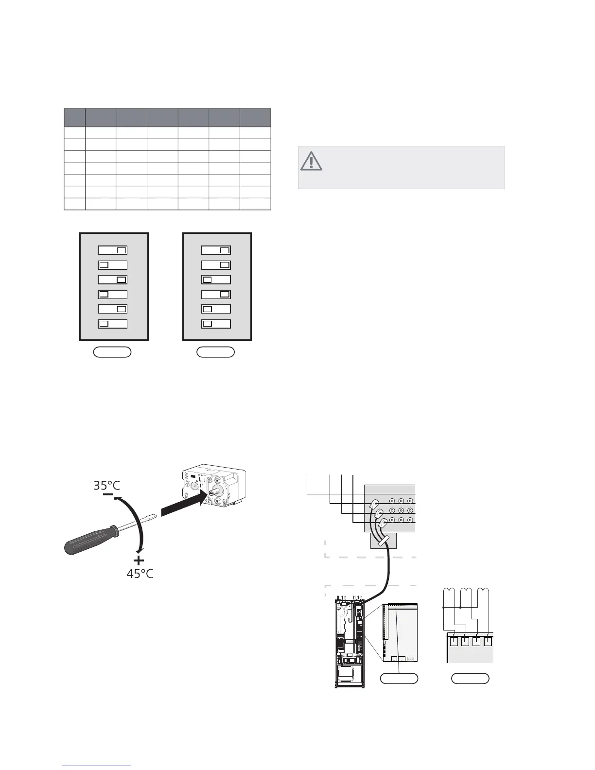
654321
onoffoffoffoffoff1kW
offoffoffonoffoff2kW
onoffoffonoffoff3kW
offonoffonoffoff4kW
onoffoffonoffon5kW
offonoffonoffon6kW
ononoffonoffon7kW
3x230V3x400V/1x230V
1 2 3 4 5 6
ON
$$6)
1 2 3 4 5 6
ON
$$6)
The image shows the dip-switch (AA1-SF2) in the factory
setting, that is 6 kW.
Emergency mode thermostat
The supply temperature is set in emergency mode using
a thermostat (FD1-BT30). It can be set to 35 (pre-set, for
example underfloor heating) or 45 °C (for example radi-
ators).
LEK
Optional connections
Load monitor
NOTE
The load monitor has no function in a 1-phase
installation.
When many power consumers are connected in the
property at the same time as the electric addition is oper-
ating, there is a risk of the property's main fuse tripping.
The heat pump has integrated load monitors that control
the electrical steps for the electrical addition by redistrib-
uting the power between the different phases or disen-
gaging. Reconnection occurs when other current con-
sumption is reduced.
Connecting current sensors
A current sensor should be installed on each incoming
phase conductor in to the distribution box to measure
the current. The distribution box is an appropriate install-
ation point.
Connect the current sensors to a multi-core cable in an
enclosure next to the distribution box. Use a multi-core
cable of at least 0.5 mm2 from the enclosure to the heat
pump.
Connect the cable to the input card (AA3) on terminal
block X4:1-4 where X4:1 is the common terminal block
for the three current sensors.
The size of the property’s main fuse is set in menu 5.1.12.
Inkommande el
LPEN
1
L
2
L
3
Elcentral
Värmepump
$$; $$;
(OHFWULFDO GLVWULEXWLRQ
XQLW
+HDW SXPS
,QFRPLQJ HOHFWULFLW\
7 7 7
23Chapter 5 | Electrical connectionsNIBE™ F1245

 Loading...


