VV
KV
KBin
VBf
VBr
KBut
BK / JK
Stängs
P
;/ ;/
&ROOHFWRU
&ORVHV
$OW $OW
;/ ;/ ;/;/ ;/ ;/
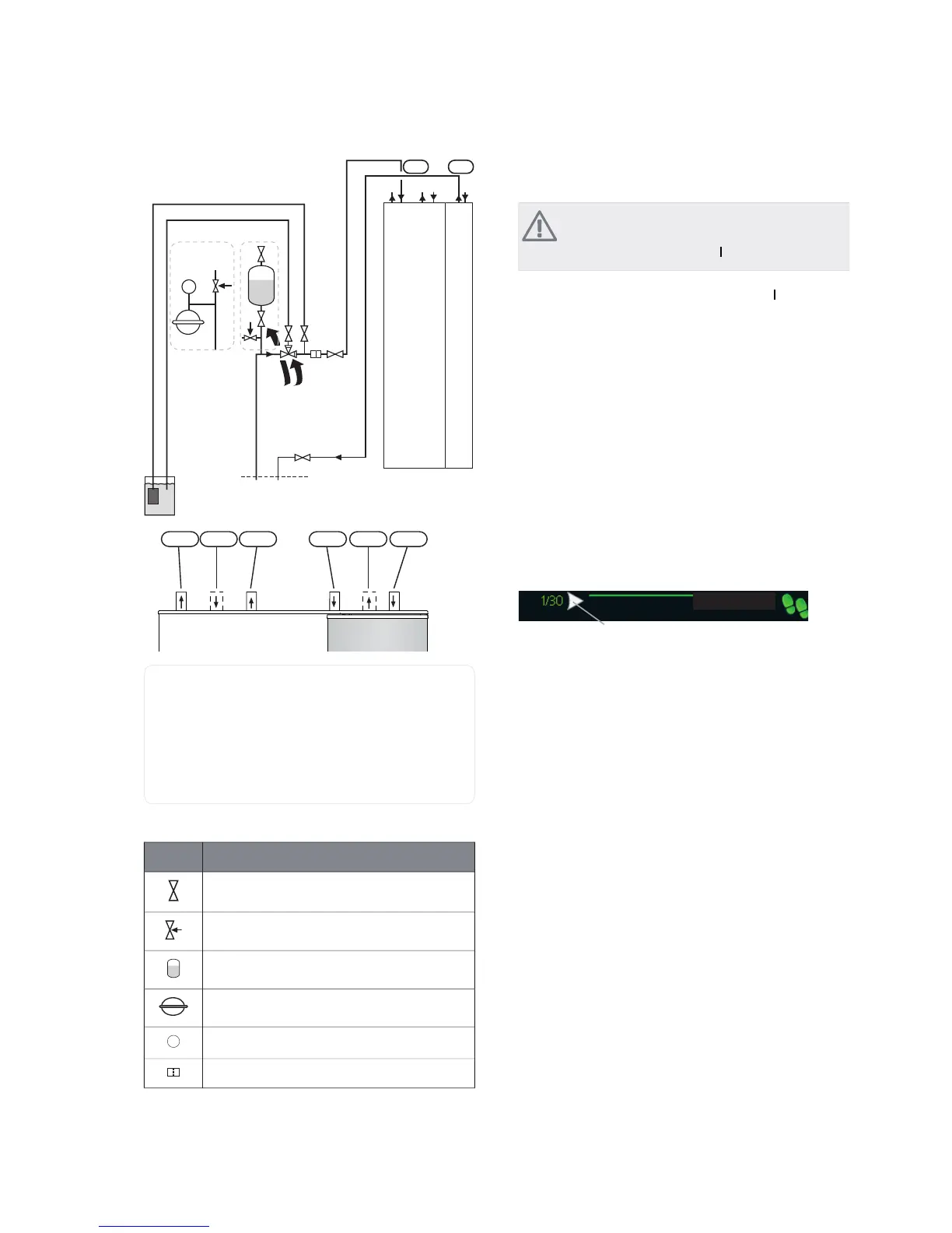
Connection, heating medium flowXL 1
Connection, heating medium returnXL 2
Connection, cold waterXL 3
Connection, hot waterXL 4
Connection, brine inXL 6
Connection, brine outXL 7
Symbol key
MeaningSymbol
Shut-off valve
Safety valve
Level vessel
Expansion vessel
Pressure gauge
P
Particle filter
Start guide
NOTE
There must be water in the climate system be-
fore the switch is set to "
".
1.
Turn the heat pump's switch (SF1) to "".
2.
Follow the instructions in the start guide in the heat
pump display. If the start guide does not start when
you start the heat pump, start it manually in menu
5.7.
Commissioning
The first time the heat pump is started a start guide is
started. The start guide instructions state what needs to
carried out at the first start together with a run through
of the heat pump’s basic settings.
The start guide ensures that the start-up is carried out
correctly and cannot be bypassed. The start guide can be
started later in menu 5.7.
Operation in the start guide
VWDUW JXLGH
$UURZV WR VFUROO WKURXJK ZLQGRZ LQ VWDUW JXLGH
1.
Turn the control knob until one of the arrows in the
top left corner (at the page number) has been
marked.
2.
Press the OK button to skip between the steps in the
start guide.
See page 42 for a more in-depth introduction to the heat
pump’s control system.
The start guide will be described under the following
points step-by-step.
NIBE™ F1245Chapter 6 | Commissioning and adjusting28

 Loading...


