Connecting the brine side
႑
Insulate all indoor brine pipes against condensation.
႑
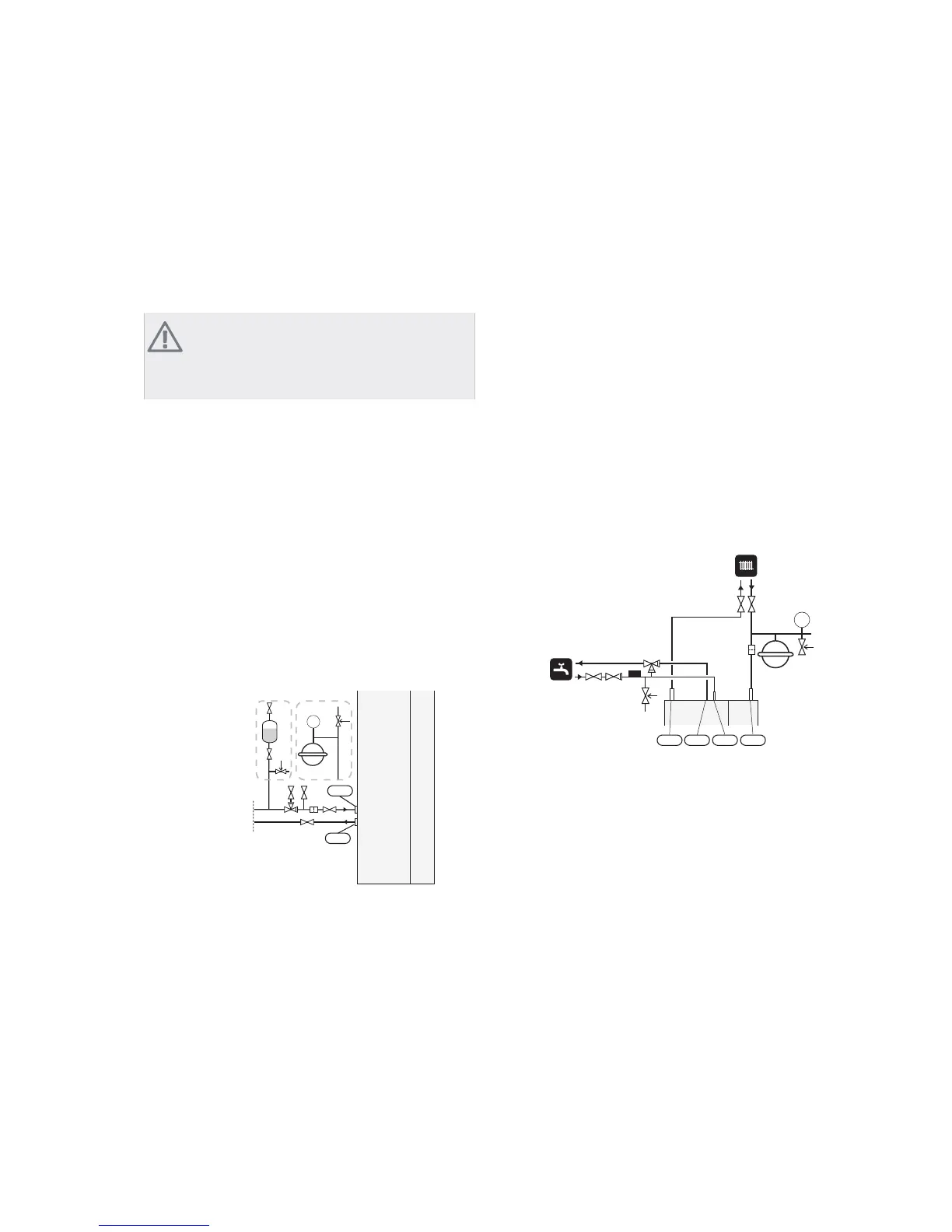
The level vessel must be installed as the highest point
in the brine system on the incoming pipe before the
brine pump (Alt. 1).
If the level vessel cannot be placed at the highest point
an expansion vessel must be used (Alt. 2).
NOTE
Note that condensation may drip from the level
vessel. Position the vessel so that this does not
harm other equipment.
႑
Details of the antifreeze used must be shown on the
level vessel.
႑
Install the supplied safety valve under the level vessel
as illustrated. The entire length of the overflow water
pipe from the safety valves must be inclined to prevent
water pockets and must also be frost proof.
႑
Install shut off valves as close to the heat pump as
possible.
႑
Fit the supplied particle filter on the incoming pipe.
In the case of connection to an open groundwater system,
an intermediate frost-protected circuit must be provided,
because of the risk of dirt and freezing in the evaporator.
This requires an extra heat exchanger.
P
;/
;/
&ROOHFWRU
$OW $OW
Heating medium side
Connecting the climate system
A climate system is a system that regulates indoor comfort
with the help of the control system in F1245 and for ex-
ample radiators, underfloor heating/cooling, fan con-
vectors etc.
႑
Install all required safety devices, shut-off valves (as
close to the heat pump as possible), and supplied
particle filter.
႑
The safety valve must have a maximum 0.25 MPa (2.5
bar) opening pressure and be installed on the outgo-
ing heating medium as illustrated. The entire length
of the overflow water pipe from the safety valves must
be inclined to prevent water pockets and must also
be frost proof.
႑
When connecting to a system with thermostats on
all radiators, a relief valve must be fitted, or some of
the thermostats must be removed to ensure sufficient
flow.
P
;/ ;/ ;/ ;/
Hot water heater
Connecting the hot water heater
႑
The hot water heater in the heat pump must be sup-
plied with necessary set of valves.
႑
The mixing valve must be installed if the setting is
changed so that the temperature can exceed 60 °C.
The setting is made in menu 5.1.1 (page 61)
႑
The safety valve must have a maximum 1.0 MPa (10.0
bar) opening pressure and be installed on the incom-
ing domestic water line as illustrated. The entire length
of the overflow water pipe from the safety valves must
be inclined to prevent water pockets and must also
be frost proof.
NIBE™ F1245Chapter 4 | Pipe connections14

 Loading...


