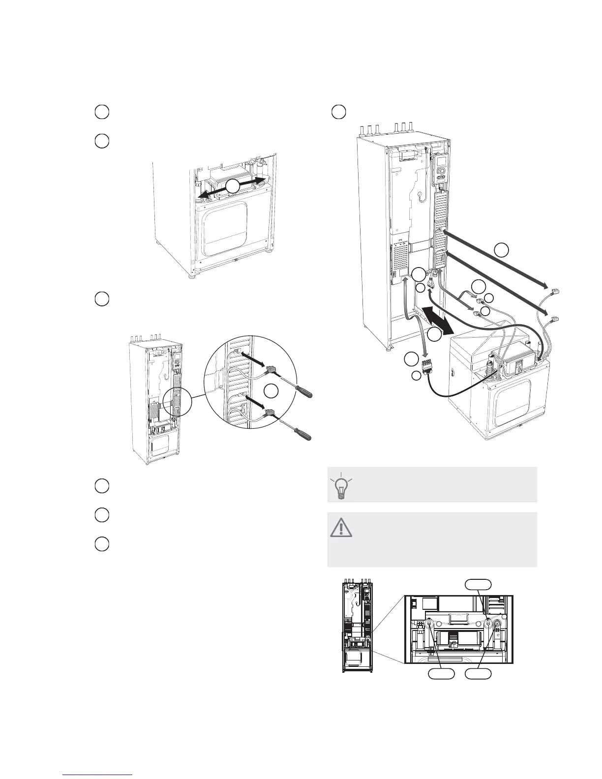
Disconnect the pipe connection at the pipe coupling
(WP4).
3
Remove the two screws.
4
L
EK
Remove the connections from the base card (AA2)
using a screwdriver.
5
L
EK
Disconnect the connectors (A) and (B) from the un-
derside of the base card cabinet.
6
Disconnect the connector (C) from the immersion
heater circuit board (AA1) using a screwdriver.
7
Disconnect the connector (D) from the joint circuit
board (AA100).
8
Carefully pull out the cooling module.
9
L
EK
$
%
&
'
TIP
The cooling module is installed in reverse order.
NOTE
At reinstallation, the supplied O-rings must re-
place the existing ones at the connections to the
heat pump (see image).
40
4040
NIBE™ F1245Chapter 9 | Service70

 Loading...


