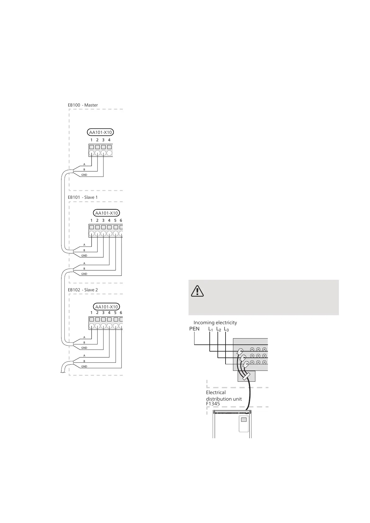
Incoming communications cables from Master or Slave
to Slave are connected to the terminal block AA101-
X10:1 (A), AA101-X10:2 (B) and AA101-X10:3 (GND), as
illustrated.
Incoming communications cables from Slave to Slave
are connected to terminal block AA101-X10:4 (A),
AA101-X10:5 (B) and AA101-X10:6 (GND), as illustrated.
Use cable type LiYY, EKKX or similar.
1 2 3 4
1 2 3 4 5 6 7
1 2 3 4 5 6 7
A
B
GND
A
B
GND
A
B
GND
A
B
GND
A
B
GND
EB100 - Master
EB101 - Slave 1
EB102 - Slave 2
AA101-X10
AA101-X10
AA101-X10
LOAD MONITOR
When many power consumers are connected in the
property at the same time as the electric additional heat
is in operation, there is a risk of the property’s main
fuses tripping. F1345 has an integrated load monitor
that controls the power steps for the electric additional
heat by disconnecting step by step in event of overload
in a phase. Reconnection occurs when other current
consumption is reduced.
Connecting current sensors
A current sensor (BE1 - BE3) must be installed on each
incoming phase conductor into the electrical distribution
unit, to measure the current. The electrical distribution
unit is an appropriate installation point.
Connect the current sensors to a multi-core cable in an
enclosure directly adjacent to the electrical distribution
unit. The multi-core cable between the enclosure and
F1345 must have a cable area of at least 0.5 mm².
Connect the cable to terminal block AA101-X10:15 to
AA101-X10:16 and AA101-X10:17 as well as to the
common AA101-X10:18 terminal block for the three
current sensors.
The value for the size of the fuse is set in menu 5.1.12
to correspond with the size of the property’s main fuse.
Here it is also possible to adjust the current sensor’s
transformer ratio.
Enclosed current sensors have a transformer ratio of
300 and, if these are used, the incoming current must
not exceed 50 A.
NOTE
The voltage from the current sensor to the in-
put board must not exceed 3.2 V.
Electrical
distribution unit
Incoming electricity
27Chapter 5 | Electrical connectionsNIBE F1345

 Loading...


