Brine side
COLLECTOR
Caution
The length of the collector hose varies depend-
ing on the rock/soil conditions, climate zone
and on the climate system (radiators or under-
floor heating) and the heating requirement of
the building Each installation must be sized in-
dividually.
Max. length per coil for the collector should not exceed
500 m.
The collectors must always be connected in parallel with
the possibility of adjusting the flow for the relevant coil.
For surface soil heat, the hose should be buried at a
depth determined by local conditions and the distance
between the hoses should be at least 1 metre.
For several bore holes, the distance between the holes
must be determined according to local conditions.
Ensure the collector hose rises constantly towards the
heat pump to avoid air pockets. If this is not possible,
airvents should be used.
Because the temperature of the brine system may fall
below 0 °C, it must be protected against freezing down
to -15 °C. When making the volume calculation, 1 litres
of ready mixed brine per metre of collector hose (applies
when using PEM-hose 40x2.4 PN 6.3) is used as a guide
value.
Caution
Because the temperature of the brine system
varies depending on the heat source, the 5.1.7
“br pmp al set.” menu must be set to a suit-
able value.
CONNECTING THE BRINE SIDE
• The pipe connections are on the rear of the heat pump.
• Insulate all indoor brine pipes against condensation.
NOTE
Condensation may drip from the expansion
vessel. Position the vessel so that this does
not harm other equipment.
Caution
When necessary you should install venting
valves in the brine system.
• Mark the brine system with the antifreeze that is used.
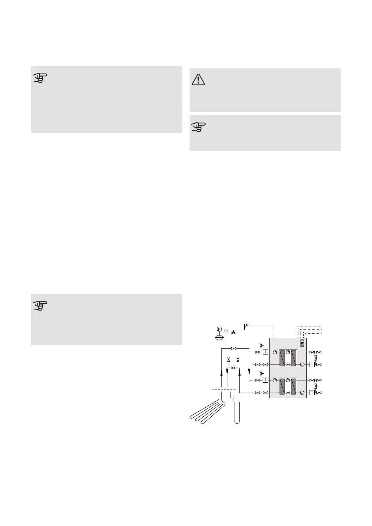
• Install the supplied safety valve at the expansion ves-
sel as illustrated in the outline diagram. The entire
length of the overflow water pipe from the safety
valves must be inclined to prevent water pockets and
must also be frost-free.
• Install shut off valves as close to the heat pump as
possible so that the flow to individual cooling modules
can be shut off. Extra safety valves between the
particle filter and shut off valves (according the outline
diagram) are required.
• Fit the supplied particle filter on the incoming pipe.
• Fit the supplied non-return valves on the outgoing
pipe.
In the case of connection to an open groundwater sys-
tem, an intermediate frost-protected circuit must be
provided, because of the risk of dirt and freezing in the
evaporator. This requires an extra heat exchanger.
NIBE F1345Chapter 4 | Pipe connections18

 Loading...


