General
Pipe installation must be carried out in accordance with
current standards and directives. F1345 can operate
with a return temperature of up to 58 °C and an outgoing
temperature of 65 °C.
F1345 is not equipped with internal shut-off valves; in-
stead, these should be installed to facilitate any future
servicing. In addition, non-return valves and particle fil-
ters must be fitted.
NOTE
The pipe systems have to be flushed clean
before F1345 is connected, to prevent any
contaminants from damaging the components.
NOTE
Do not solder directly on the pipes in F1345,
because of internal sensors.
Compression ring coupling alternatively pres-
sure connection should be used.
NOTE
The heating system's pipes must be earthed
to prevent a potential difference between them
and the building's protective earth.
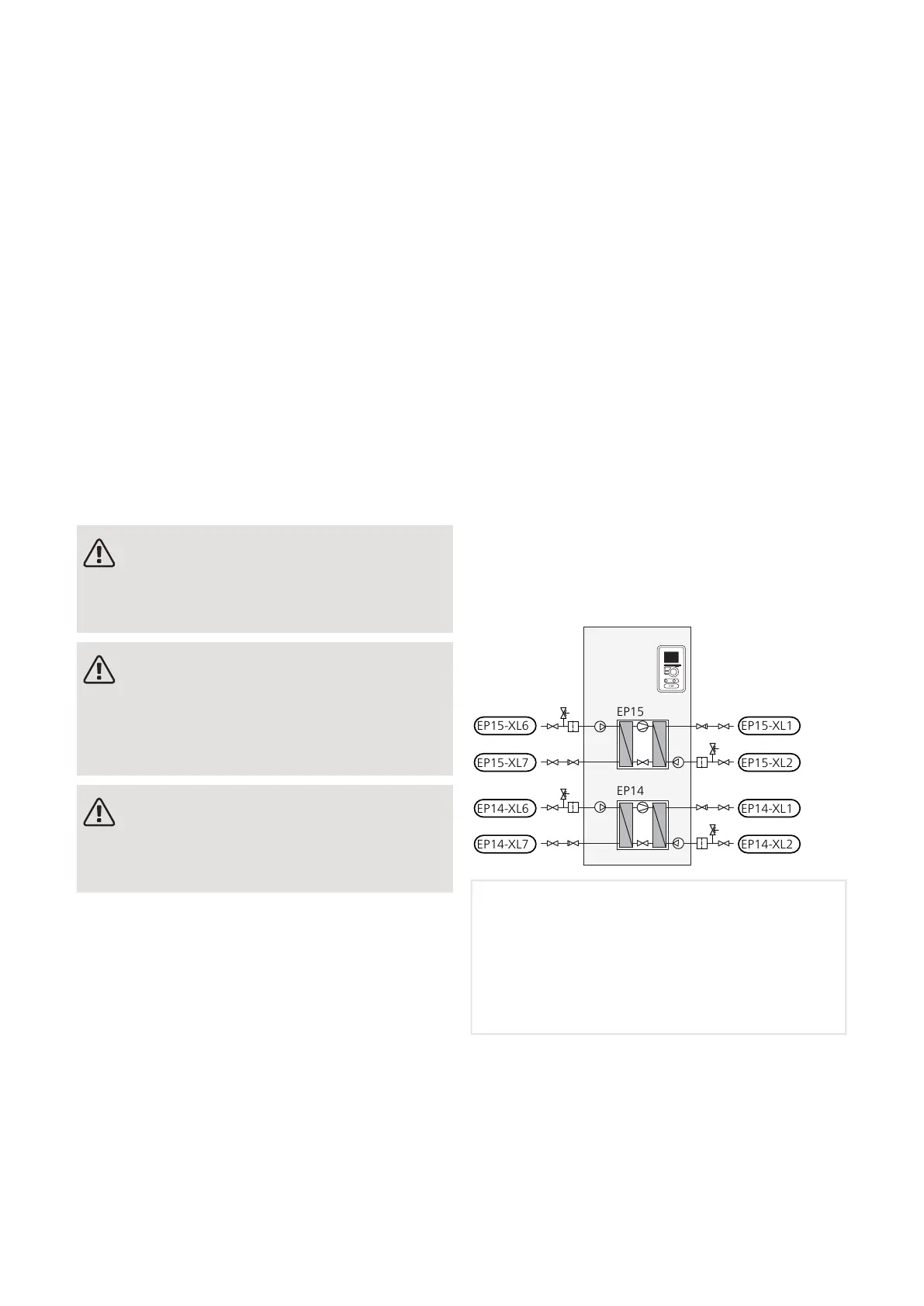
SYMBOL KEY
SYSTEM DIAGRAM
F1345 consists of two heat pump modules, circulation
pumps and control system with possibility of additional
heat. F1345 is connected to the brine and heating medi-
um circuits.
In the heat pump evaporator, the brine (water mixed
with anti-freeze, glycol or ethanol) releases its energy
to the refrigerant, which is vaporised in order to be
compressed in the compressor. The refrigerant, of which
the temperature has now been raised, is passed to the
condenser where it gives off its energy to the heating
medium circuit and, if necessary, to any docked water
heater. If there is a greater need for heating/hot water
than the compressors can provide it is possible is to
connect an external immersion heater.
EP15-XL1
EP15-XL2
EP15-XL6
EP15-XL7
EP14-XL1
EP14-XL2
EP14-XL6
EP14-XL7
EP15
EP14
Cooling moduleEP14
Cooling moduleEP15
Connection, heating medium flowXL1
Connection, heating medium returnXL2
Connection, brine inXL6
Connection, brine outXL7
NIBE F1345Chapter 4 | Pipe connections16
4 Pipe connections

 Loading...


