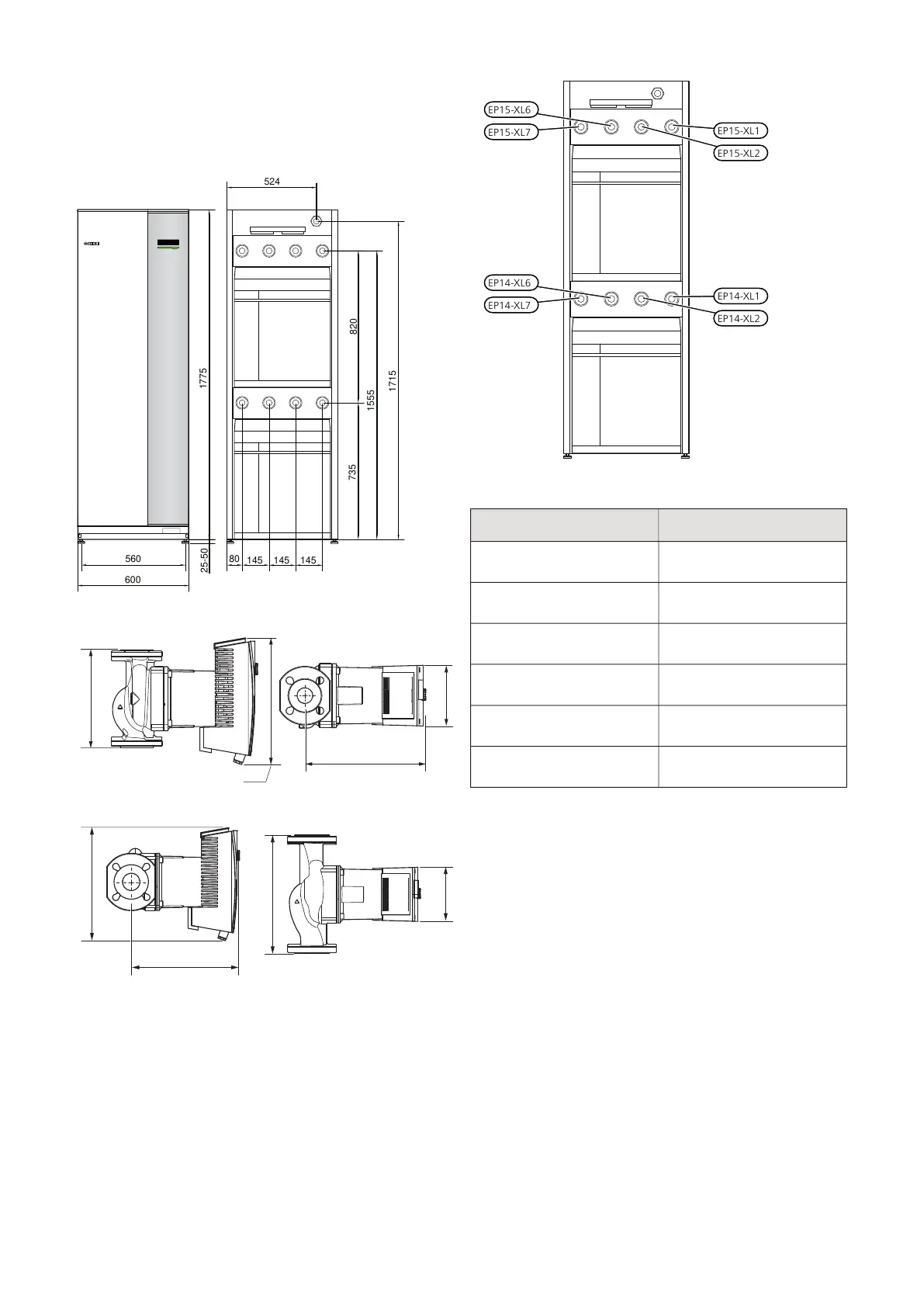
EasyManuals Logo

Nibe F1345 Series User Manual

Nibe F1345 Series
68 pages
To Next Page IconTo Next Page
To Previous Page IconTo Previous Page
Page #17 background imageLoading...
Page #17 background image
Dimensions and pipe
connections
1775
600
560
440
735
1555
1715
80
145
145
145
450620
820
85
25-50
1775
600
560
440
735
1555
1715
80
145
145
145
524620
820
85
25-50
External brine pump 40 kW
250
325
155
309
External brine pump 60 kW
325
155
340
311
EP15-XL6
EP15-XL7
EP14-XL6
EP14-XL7
EP15-XL1
EP15-XL2
EP14-XL1
EP14-XL2
PIPE DIMENSIONS
Connection
internal thread G
external thread G2
(XL1) Heating medium sup-
ply
internal thread G
external thread G2
(XL2) Heating medium re-
turn
internal thread G
external thread G2
(XL6) Brine in
internal thread G
external thread G2
(XL7) Brine out
compression ring coupling
Ø 42mm
External brine pump 40 kW
compression ring coupling
Ø 54mm
External brine pump 60 kW
17Chapter 4 | Pipe connectionsNIBE F1345

Questions and Answers:

Question and Answer IconNeed help?

Do you have a question about the Nibe F1345 Series and is the answer not in the manual?

Nibe F1345 Series Specifications

General IconGeneral
RefrigerantR410A
Control SystemNIBE SMO 40
Max Flow Temperature65°C
Cooling CapacityNot explicitly stated in general specifications. Depends on the specific model and installation conditions.
COP4.5
Electrical Connection400V 3N~
EER (Cooling)Not explicitly stated in general specifications. Depends on the specific model and installation conditions.
Number of Compressors1 or 2 (depending on model)

Related product manuals