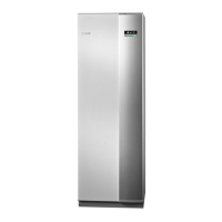
Docking alternatives
F1345 can be connected in several different ways. Ex-
amples are shown below.
Caution
The examples are outline diagrams; items in-
cluded on delivery of the product are set out
in section"Supplied components".
Further information about the options is available at
nibe.eu and in the manuals for the accessories used.
See page 42 for the list of the accessories that can be
used with F1345.
EXPLANATION
External additional heatEB1
External electrical additional heatEB1
Safety valve, heating medium sideFL10
Shut-off valve, heating medium sideQM42, QM43
Trim valveRN11
Heat pump systemEB100, EB101
Temperature sensor, outdoorBT1
Temperature sensor, hot water chargingBT6
Temperature sensor, heating medium
flow, external
BT25
Temperature sensor, heating medium
return, external
BT71
Heat pump F1345 (Master)EB100
Heat pump F1345 (Slave)EB101
Cooling moduleEP14, EP15
Safety valve, collector sideFL10, FL11
Safety valve, heating medium sideFL12, FL13
Particle filterHQ12 - HQ15
Shut-off valve, brine sideQM50 - QM53
Shut-off valve, heating medium sideQM54 - QM57
Reversing valve, heating/hot waterQN10
Non-return valveRM10 - RM13
Hot water circulationQZ1
Accessory cardAA5
Temperature sensor, hot water flowBT70
Mixer valve, hot waterFQ1
Circulation pump, domestic hot water
circulation
GP11
Non-return valveRM23, RM24
Trim valveRN20, RN21
Climate system 2EP21
Temperature sensors, heating medium
flow
BT2
Temperature sensors, heating medium
return
BT3
Circulation pumpGP20
Shunt valveQN25
Miscellaneous
Accessory cardAA5
Manometer, brine sideBP6
Temperature sensor, hot water flowBT7
Storage tankCP5
Expansion vessel, closed, heating medi-
um side
CM1
Expansion vessel, closed, brine sideCM3
Additional water heaterCP4
Collector, brine sideEP12
Safety valve, heating medium sideFL2
Safety valve, brineFL3
Circulation pump, heating medium extern-
al
GP10
Venting valve, brine sideQM21
Shut off valve, brine flowQM33
Shut off valve, brine returnQM34
Non-return valveRM21
Connection, filling brineXL27 - XL28
21Chapter 4 | Pipe connectionsNIBE F1345

 Loading...