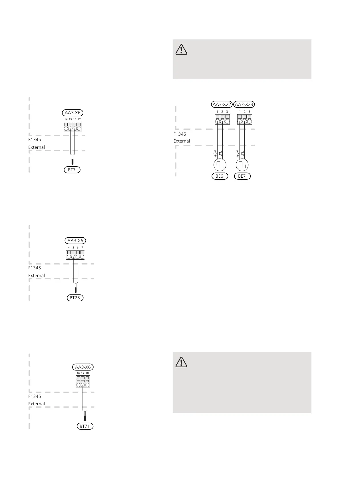
TEMPERATURE SENSOR, HOT WATER TOP
(BT7)
A temperature sensor for hot water top (BT7) can be
connected to F1345 for showing the water temperature
at the top of the tank (if possible).
Connect the sensor to terminal block AA3-X6:15 and
AA3-X6:16. Use a twin core cable with a cable area of
at least 0.5 mm².
TEMPERATURE SENSOR, EXTERNAL SUPPLY
LINE (BT25)
Connect temperature sensor, external supply line (BT25)
to terminal block AA3-X6:5 and AA3-X6:6. Use a twin
core cable with a cable area of at least 0.5 mm².
TEMPERATURE SENSOR, EXTERNAL
RETURN LINE (BT71)
Connect temperature sensor, external return line (BT71)
to terminal block AA3-X6:17 and AA3-X6:18. Use a twin
core cable with a cable area of at least 0.5 mm².
CONNECTING EXTERNAL ENERGY METER
NOTE
Connection of external energy meter requires
version 35 or later on input board (AA3) as well
as "display version" 7157R3 or later.
One or two energy meters (BE6, BE7) are connected to
terminal block X22 and/or X23 on input board (AA3).
F1345
E
xternt
1 2 3 1 2 3
+5V
+5V
External
F1345
AA3-X22
BE6
AA3-X23
BE7
Activate the energy meter(s) in menu 5.2.4 and then set
the desired value (energy per pulse) in menu 5.3.21.
Optional connections
MASTER/SLAVE
Several heat pumps can be interconnected by selecting
one heat pump as master and the others as slaves.
Ground source heat pump models with master/slave
functionality from NIBE can be connected to F1345.
The heat pump is always delivered as master and up to
till 8 slaves can be connected to it. In systems with
several heat pumps, each pump must have a unique
name, i.e. only one heat pump can be "Master" and only
one can be e.g. "Slave 5". Set master/slaves in menu
5.2.1.
External temperature sensors and control signals must
be connected solely to the master, except for external
control of the compressor module and reversing valve(s)
(QN10) that can be connected one to each heat pump.
See page 31 for connecting the reversing valve (QN10).
NOTE
When several heat pumps are connected to-
gether (master/slaves), an external supply
temperature sensor (BT25) and an external re-
turn sensor BT71 must be used. If these
sensors are not connected, the product will
give a sensor fault.
Connect the communications cables to the Master’s
terminal block AA101-X10:1 (A), AA101-X10:2 (B) and
AA101-X10:3 (GND), as illustrated.
NIBE F1345Chapter 5 | Electrical connections26

 Loading...


