REVERSING VALVES
F1345 can be supplemented with an external reversing
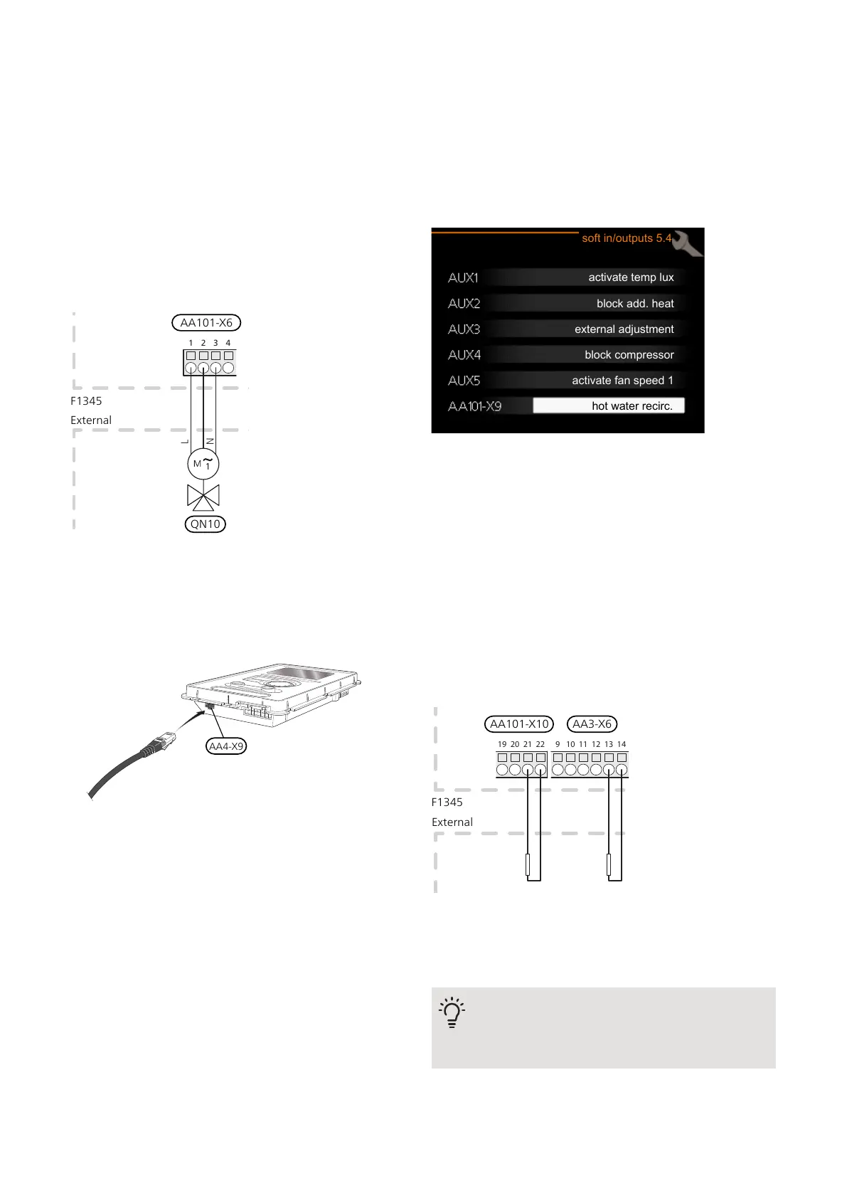
valve (QN10) for hot water control (see page 42 for ac-
cessory).
Connect the external reversing valve (QN10) to terminal
block AA101-X6:3 (N), AA101-X6:2 (operation) and
AA101-X6:1 (L) as illustrated.
With several heat pumps connected as master/slave,
connect the reversing valve electrically to a suitable heat
pump. The reversing valve is controlled by the master
heat pump regardless which heat pump it is connected
to.
External
F1345
QN10
AA101-X6
NIBE UPLINK
Connect a network-connected cable (straight, Cat.5e
UTP) with RJ45 contact (male) to contact AA4-X9 on the
display unit (as illustrated). Use the cable grommet (UB3)
on the heat pump for cable routing.
EXTERNAL CONNECTION OPTIONS (AUX)
F1345 has software-controlled AUX inputs and outputs
on the input board (AA3), for connecting the external
switch function or sensor. This means that when an
external switch function (the switch must be potential-
free) or sensor is connected to one of six special con-
nections, this function must be selected for the correct
connection in menu 5.4.
block add. heat
external adjustment
block compressor
activate fan speed 1
soft in/outputs 5.4
hot water recirc.
activate temp lux
For certain functions, accessories may be required.
Selectable inputs
Selectable inputs on the input board for these functions
are:
AA3-X6:9-10AUX1
AA3-X6:11-12AUX2
AA3-X6:13-14AUX3
Selectable inputs on terminal block AA101-X10 for these
functions are:
AA101-X10:19-20AUX4
AA101-X10:21-22AUX5
Externt
9 10 11 12 13 14
19 20 21 22
External
F1345
AA101-X10 AA3-X6
The example above uses the inputs AUX3 (AA3-X6:13-14) and AUX5
(AA101-X10:21-22) on the terminal block.
Selectable output
A selectable output is AA101-X9.
TIP
Some of the following functions can also be
activated and scheduled via menu settings.
31Chapter 5 | Electrical connectionsNIBE F1345

 Loading...


