ADDITIONAL HEAT IN TANK
NOTE
Mark up any junction boxes with warnings for
external voltage.
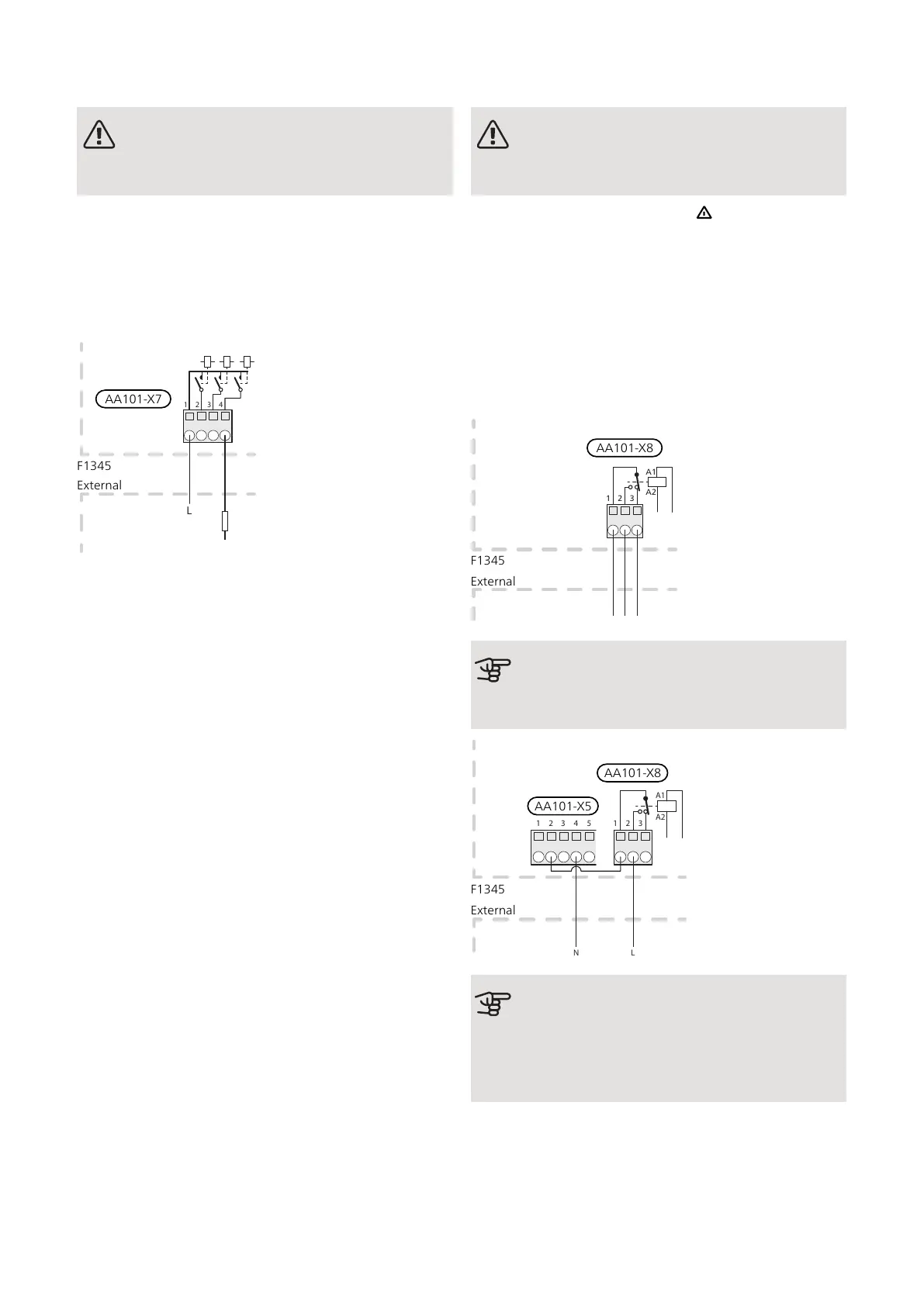
This connection allows an external additional heater in
the tank to assist with the production of hot water when
the compressors are busy producing heating.
Additional heat in tank is activated in menu 5.1.12.
To control switching the additional heat on and off in
the tank, connect it to terminal block AA101-X7:4.
All additional heat can be blocked by connecting a poten-
tial-free switch function to AUX input on terminal block
AA3-X6 and AA101-X10. The function must be activated
in menu 5.4.
RELAY OUTPUT FOR EMERGENCY MODE
NOTE
Mark up any junction boxes with warnings for
external voltage.
When the switch (SF1) is set to " " mode (emergency
mode), the internal circulation pumps (EP14-GP1 and
EP15-GP1) and the potential-free variable emergency
mode relay (AA101-K4) are activated. External accessor-
ies are disconnected.
The emergency mode relay can be used to activate ex-
ternal additional heat, an external thermostat must then
be connected to the control circuit to control the temper-
ature. Ensure that the heating medium circulates through
the external additional heating.
Caution
No hot water is produced when emergency
mode is activated.
Externt
1 2 3
A1
A2
1 2 3 4
N L
5
External
F1345
AA101-X5
AA101-X8
Caution
If the relays are to be used for operating
voltage, bridge the supply from AA101-X5:1 -
3 to AA101-X8:1. Connect the neutral from the
external additional heat to AA101-X5:4 - 6.
NIBE F1345Chapter 5 | Electrical connections30

 Loading...


