STEP CONTROLLED ADDITIONAL HEAT
NOTE
Mark up any junction boxes with warnings for
external voltage.
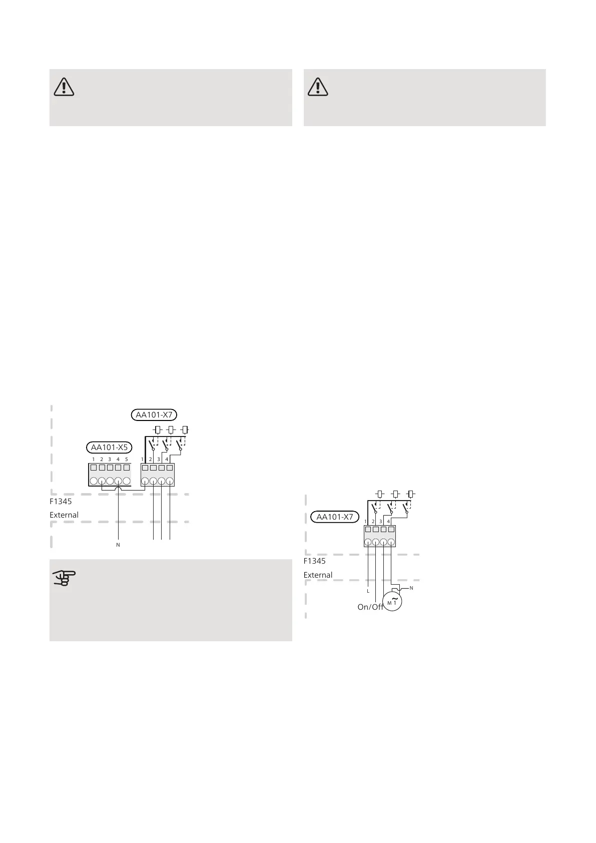
External step-controlled additional heat can be controlled
by up to three potential-free relays in F1345 (3 step linear
or 7 step binary). With the AXC 50 accessory, a further
three potential-free relays are used for additional heat
control, which then gives max 3+3 linear or 7+7 binary
steps.
Step in occurs with at least 1 minute interval and step
outs with at least 3 seconds interval.
Connect the common phase to terminal block AA101-
X7:1.
Step 1 is connected to terminal block AA101-X7:2.
Step 2 is connected to terminal block AA101-X7:3.
Step 3 is connected to terminal block AA101-X7:4.
The settings for step controlled additional heat are made
in menu 4.9.3 and menu 5.1.12.
All additional heat can be blocked by connecting a poten-
tial-free switch function to AUX input on terminal block
AA3-X6 and AA101-X10. The function must be activated
in menu 5.4.
External
F1345
AA101-X5
AA101-X7
Caution
If the relays are to be used for operating
voltage, bridge the supply from AA101-X5:1 -
3 to AA101-X7:1. Connect the neutral from the
external additional heat to AA101-X5:4 - 6.
SHUNT CONTROLLED ADDITIONAL HEAT
NOTE
Mark up any junction boxes with warnings for
external voltage.
This connection enables an external additional heater,
e.g. an oil boiler, gas boiler or district heating exchanger
to aid with heating.
The connection requires that the boiler sensor (BT52)
is connected to one of the AUX inputs in F1345, see
page 32. The sensor is only selectable when “shunt
controlled add. heat” is selected in menu 5.1.12.
F1345 controls a shunt valve and start signal for the
additional heating using three relays. If the unit does not
manage to maintain the correct supply temperature, the
additional heat starts. When the boiler sensor (BT52)
exceeds the set value, F1345 sends a signal to the shunt
(QN11) to open from the additional heat. The shunt
(QN11) is controlled to ensure the true supply temperat-
ure corresponds with the control system’s theoretically
calculated set point value. When the heating demand
drops sufficiently so that additional heat is no longer
required, the shunt (QN11) closes completely. Factory-
set minimum operating time for the boiler is 12 hours
(can be adjusted in menu 5.1.12).
The settings for shunt controlled additional heat are
made in menu 4.9.3 and menu 5.1.12.
Connect the shunt motor (QN11) to terminal block
AA101-X7:4 (230 V, open) and 3 (230 V, close).
To control switching the additional heat on and off,
connect it to terminal block AA101-X7:2.
Till/Från
1 2 3 4
Externt
L
N
M
External
F1345
On/Off
AA101-X7
All additional heat can be blocked by connecting a poten-
tial-free switch function to AUX input on terminal block
AA3-X6 and AA101-X10. The function must be activated
in menu 5.4.
29Chapter 5 | Electrical connectionsNIBE F1345

 Loading...


