Install the brine pump (GP16) according to the circulation
pump manual for connection of incoming brine (EP14-
XL6) and (EP15-XL6) between the heat pump and shut-
off valve (see image).
NOTE
Insulate the brine pump against condensation
(do not cover the drainage hole).
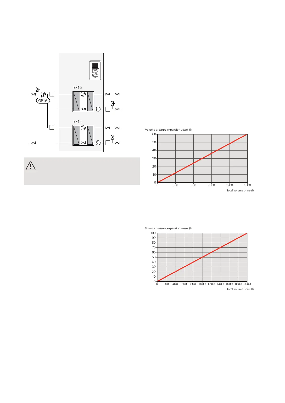
EXPANSION VESSEL
The brine circuit must be supplied with a pressure ex-
pansion vessel.
The brine side must be pressurised to at least 0.05 MPa
(0.5 bar).
The pressure expansion vessel should be dimensioned
as set out in the following diagram, to prevent malfunc-
tions. The diagrams cover the temperature range from
10 °C to +20 °C at pre-pressure 0.05 MPa (0.5 bar) and
the safety valve's opening pressure of 0.3 MPa (3.0
bar).
Ethanol 28% (volume percent)
In installations with ethanol (28% volume percent) as
the brine the pressure expansion vessel must be dimen-
sioned according to the following diagram.
0
0 300 600 12009000 1500
10
20
30
40
50
60
Volym tryckexpansionskärl
(l)
Totalvolym köldbärere i system
(l)
Volume pressure expansion vessel (l)
Total volume brine (l)
Ethylene glycol 40% (volume percent)
In installations with ethylene glycol (40% volume per-
cent) as the brine the pressure expansion vessel must
be dimensioned according to the following diagram.
0
0 200 400 600 800 1000 1200 1400 1600 1800 2000
10
20
30
40
60
70
50
80
90
100
Volym tryckexpansionskärl
(l)
Total volym köldbärare i system
(l)
Volume pressure expansion vessel (l)
Total volume brine (l)
19Chapter 4 | Pipe connectionsNIBE F1345

 Loading...


