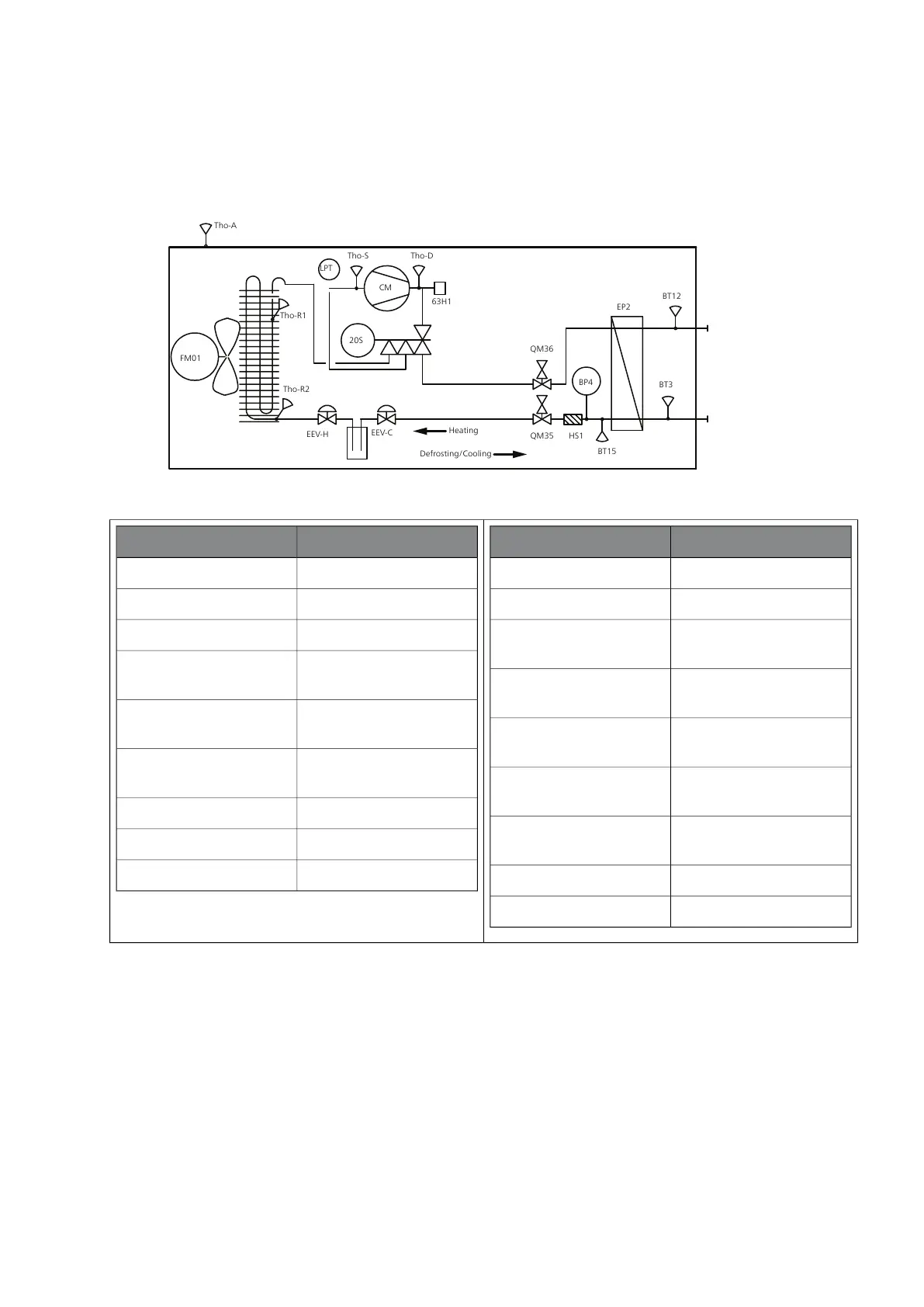
Principle of operation
Defrosting/Cooling
Tho-D
Tho-S
LPT
20S
Tho-R1
EEV-H
EEV-C
FM01
CM
63H1
BP4
BT3
BT12
EP2
BT15
HS1
Tho-A
Heating
QM36
QM35
Tho-R2
InformationDesignation
Drying filterHS1
Low pressure transmitterBP2 (LPT)
Temperature sensor, ambi-
ent
BT28 (Tho-A)
Temperature sensor, hot
gas
BT14 (Tho-D)
Temperature sensor, heat
exchanger out
BT16 (Tho-R1)
Temperature sensor, heat
exchanger, in
Tho-R2
Temperature sensor, suc-
tion gas
BT17 (Tho-S)
Service valve, liquid sideQM35
Service valve, gas sideQM36
InformationDesignation
4-way valveQN2 (20S)
High pressure pressostatBP1 (63H1)
Pressure sensor, condenserBP4
Temperature sensor, heat-
ing medium return line
BT3
Temperature sensor, con-
denser supply line
BT12
Temperature sensor, fluid
pipe
BT15
CompressorGQ10 (CM)
CondenserEP2
FanGQ1 (FM01)
NIBE™ F2040Chapter 3 | System description14
3 System description