223 - OU com error
223 OU com error
Testpunkter då PWB1 Control är "dött", inga LED tända.
POWER SOURCE 1 ~ 230V
MS
3~
PWB2 INVERTER
DM
A/F MODULE
PWB1
Varierande 0-22 VDC: OK
230V: OK
310 - 320 VDC: OK310 - 320 VDC: OK
310 - 320 VDC: OK
310 - 320 VDC: OK
NOISE FILTER PWB3
F (8A)
F (4A)
F (30A)
Y/GN
AA23
TB
Till kommunikationskort
L
L
1
L
10
N
N
N
0
2
2
2
1
1
1
3
E
E
TB
BL
C1
P1
L1 L2
P
P
+
+ –
P2
U
GN
CM
U
V
V
W
W
IPM
N1
L
N2
N2
N2
BL
BL
BL
RD
RD
RD
GN
GN
WH
CNI2
(WH)
CNF
(BK)
CNR
(WH)
CNS
(RD)
52X1
52X2
52X3
52X4
CNI1
(WH)
CNACT1
(WH)
CNI3
(WH)
Two fan
unit only
CNI4
(WH)
Ingen signal: Trasig
1
1
Kontrollera följande:
Variable 0-22 VDC: OK
No signal: Broken
To communication card
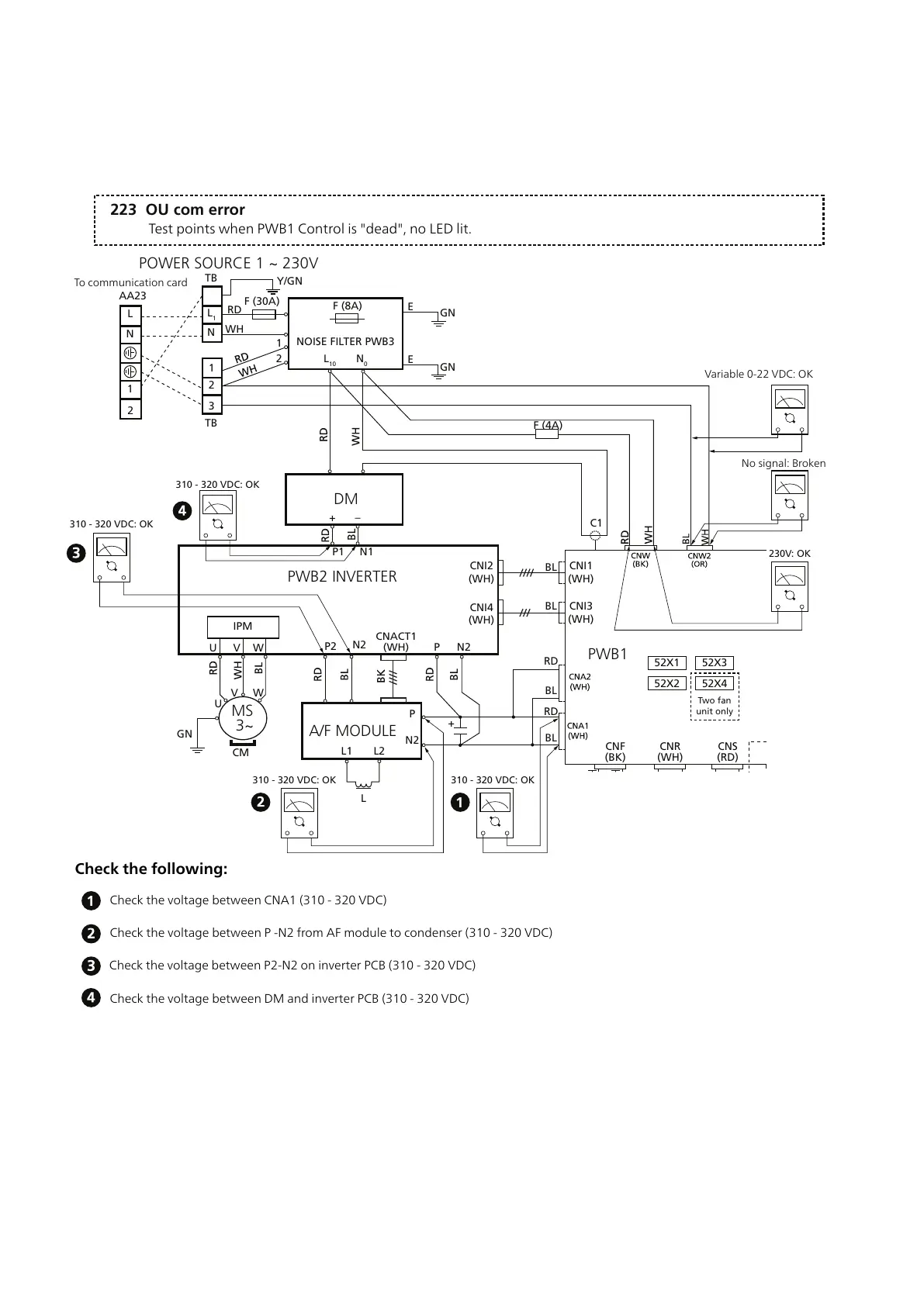
Test points when PWB1 Control is "dead", no LED lit.
Check the following:
Check the voltage between CNA1 (310 - 320 VDC)
Check the voltage between P -N2 from AF module to condenser (310 - 320 VDC)
Check the voltage between P2-N2 on inverter PCB (310 - 320 VDC)
Check the voltage between DM and inverter PCB (310 - 320 VDC)
■
CNW2 is connection for the communication cable between the indoor unit and outdoor unit so that there is an
oscillating signal 0-22VDC, but there is not a fixed voltage in it. The cable must remain in place while measuring
takes place.
■
The voltage on CNA1 and CNA2 is approx 310-320VDC with 230V measurement voltage.
■
CNA2 is supply voltage to Control PCB then Control PCB creates its own internal control voltage, where voltage
to green and red LED is included.
■
If the LED on the circuit board is not lit this voltage may be missing. Measure at points 1-4 in turn to establish
where the voltage disappears.
57Chapter 6 | TroubleshootingNIBE™ F2040