Electrical connection
FIGHTER 1220
For the Installer
18
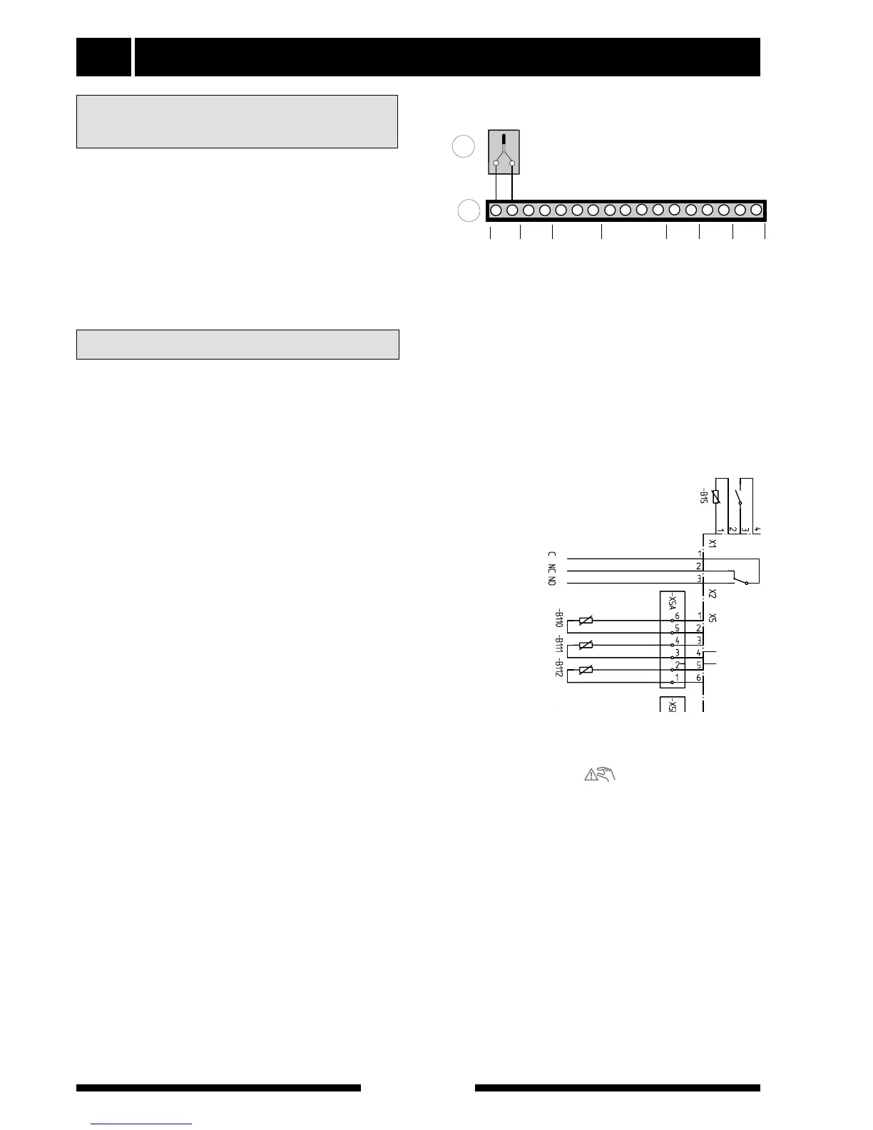
Install the outside sensor in the shade on a wall facing
north or north-west, so it is unaffected by the morning
sun. The sensor is connected with a two-wire cable to
terminal block (14) positions 1 and 2, on the load mon-
itor card (2).
If a conduit is used it must be sealed to prevent con-
densation in the sensor capsule. The minimum cable
cross section should be 0.4 mm
2
up to lengths of 50
metres, for example, EKKX or LiYY.
Alarm
A common alarm is given in the following instances:
High pressure switch (HP) has tripped. Indicated as
HP-alarm.
LP pressure switch (LP) has tripped. Indicated as an
LP alarm.
Temperature limiter (TB) has tripped. Indicated as a
TB-alarm.
The motor cut-out (MS) has tripped, indicated by an
MS-alarm.
Pressure/level monitor brine (accessory) indicated as
pressure/level brine.
Brine temp. low, indicates a low brine temperature. Not
indicated when menu 5.2 is set to automatic return On.
Supply sensor fault is indicated by a Sensor alarm.
Hot water sensor fault is indicated by a Sensor alarm.
External indication of common alarms is possible
through the relay function on the load monitor card (2).
Alarm/alarm outputs
In the event of an alarm the relay contact makes, the
figure shows the relay in the alarm position. When
switch (8) is in the 0 or “ ” position the relay is in
the alarm position.
Connecting an
outside temperature sensor