24 – English
English
9.4 - RADIO TRANSMITTERS MEMORISATION
The control unit incorporates a radio receiver for ECCO5 transmitters (var-
ious models). The transmitters supplied are not memorised, therefore it is
first necessary to memorise the 1st transmitter (Mode 1).
If you want to memorise a new radio transmitter you have two possible
choices:
• Mode 1: in this “mode” the radio transmitter is used in full, that is, all the
keys carry out a predefined command. It is clear that in mode 1 a radio
transmitter can be used to control a single automation; namely:
• Mode 2: one of the four available commands can be assigned to each
key. By using this mode correctly, you can also control 2 or more different
automations; for example:
Key Paired command
T1 “Open Only” command Automation No. 1
T2 “Close Only” command Automation No. 1
T3 “Step-by-Step (SbS)” command Automation No. 2
T4 “Step-by-Step (SbS)” command Automation No. 3
T5 Auxiliary function: not present
Naturally each transmitter is a specific case and in the same control unit
there may be some stored in mode 1 and others in mode 2.
Overall, the memory capacity is 150 units; mode 1 memorisation occu-
pies a unit for each transmitter while mode 2 occupies a unit for each key.
Caution! – Since the memorization procedures are timed (10s), you
must read the instructions in the following paragraphs before you
proceed with their execution.
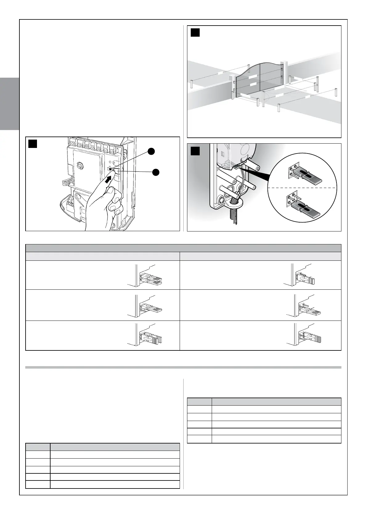
For correct photocells recognition by the control unit, you need to carry
out its addressing, through the use of suitable electrical jumpers. The
addressing operation must be carried out both on TX and RX (setting the
electrical jumpers in the same way) and by making sure there are no other
couples of photocells with the same address. The photocells addressing
serves both for correct recognition by other devices on the ECSbus, and
to assign the function performed.
01. Open the photocell housing.
02. Locate the position in which they are installed according to Figure 39
and install the jumper according to Table 8.
The unused jumpers are stored in a compartment on their reserve, to
be able to be reused in the future(fig. 40).
03. Carry out the recognition phase as described in paragraph 10.3.3
“Recognition of other devices”.
38
B
A
TABLE 8
Photocell h = 50cm activated
when gate closes
Photocell h = 100cm
activated when gate closes
Photocell h = 100cm
activated when gate opens
and closes
Photocell
Jumper
A
B
D
C
Photocell h = 50cm activated
when gate opens and closes
Left photocell activated
when gate opens
F
Right photocell activated
when gate opens
E
Photocell
Jumper
FOTO
FA 1
FA 2
FOTO II
FOTO 1
FOTO 2 II
FOTO 2
FOTO 1 II
39
40
Key Paired command
T1 Step-by-Step (SbS)
T2 Partial open
T3 Open only
T4 Close only
T5 Auxiliary function: not present