38
4. Connections
Digitax SF Instruction Manual
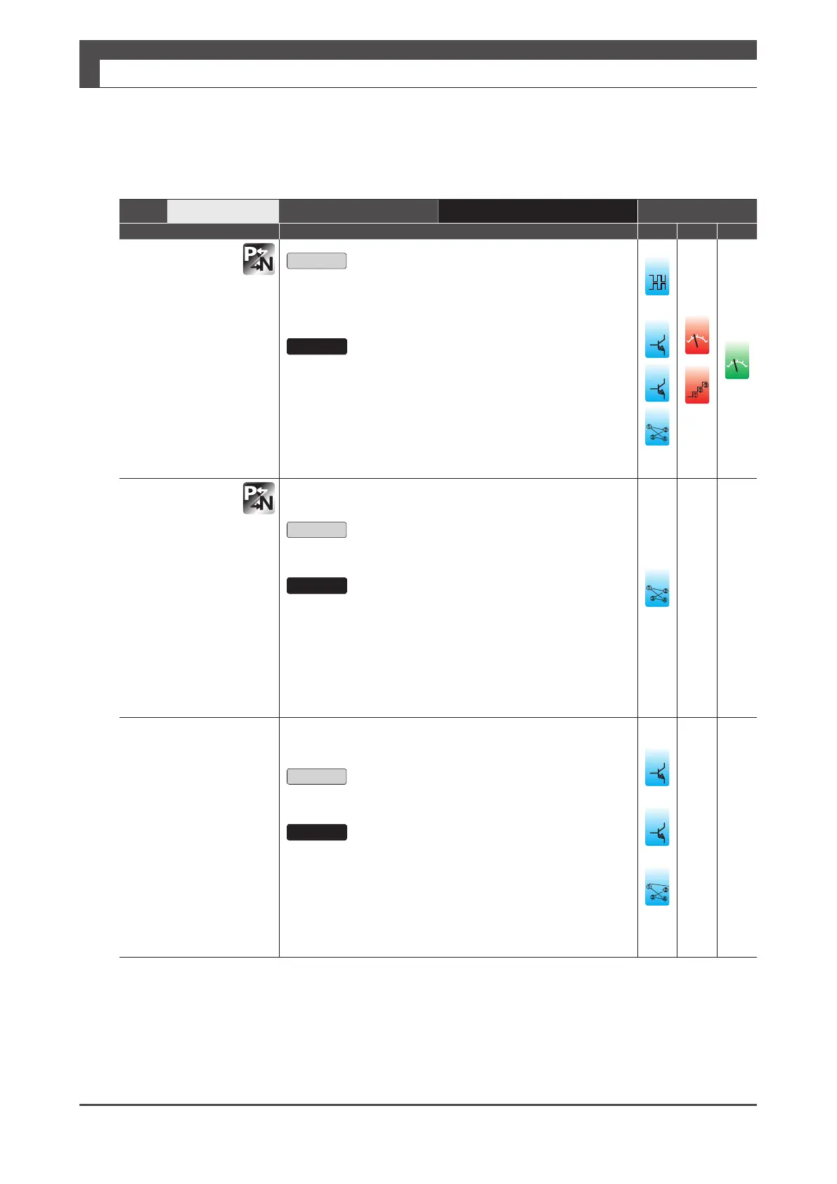
5. Descriptions of CN1 Connector Signals
Pin No.
19, 20
Interface Circuit
PO(Page 46) Control Mode
Signal Description P S T
SREDY +
(Pin No.19)
SREDY -
(Pin No.20)
Servo ready
Open
In one of the following conditions
An alarm is occurring.
The AC supply is not supplied to the drive.
Close
The following conditions are met at the same time.
No alarm is occurring.
The AC Supply is supplied to the drive.
■ TIP
The emitter side of the output transistor is independent of
COM-. Cascade connection to multiple drives is possible.
24
䐟
䐠
䐡
䐢
**
ol
䐟
䐠
ol
SERVO +
(Pin No.19)
SERVO -
(Pin No.20)
Servo status
Open
Servo-o status
Close
Servo-on status
■ TIP
The emitter side of the output transistor is independent of
COM-. Cascade connection to multiple drives is possible.
䐟
䐠
䐡
䐢
***
DBRK +
(Pin No.19)
DBRK -
(Pin No.20)
Emergency stop
brake release
Open
Engages the Emergency stop brake.
Close
Disengages the emergency stop brake.
****
5
****
i/o
䐟
䐠
䐡
䐢
1) In Standard I/O configuration
2) In Standard I/O configuration
3) In Optional I/O configuration
4) In I/O configuration Option 2
*
****
*
**
***
****
See preparation chapter to build an emergency stop
breaking circuit.