Safety information Introduction Product information System configuration
Mechanical
Installation
Electrical Installation
Unidrive M Modular Installation Guide 11
Issue Number: 2
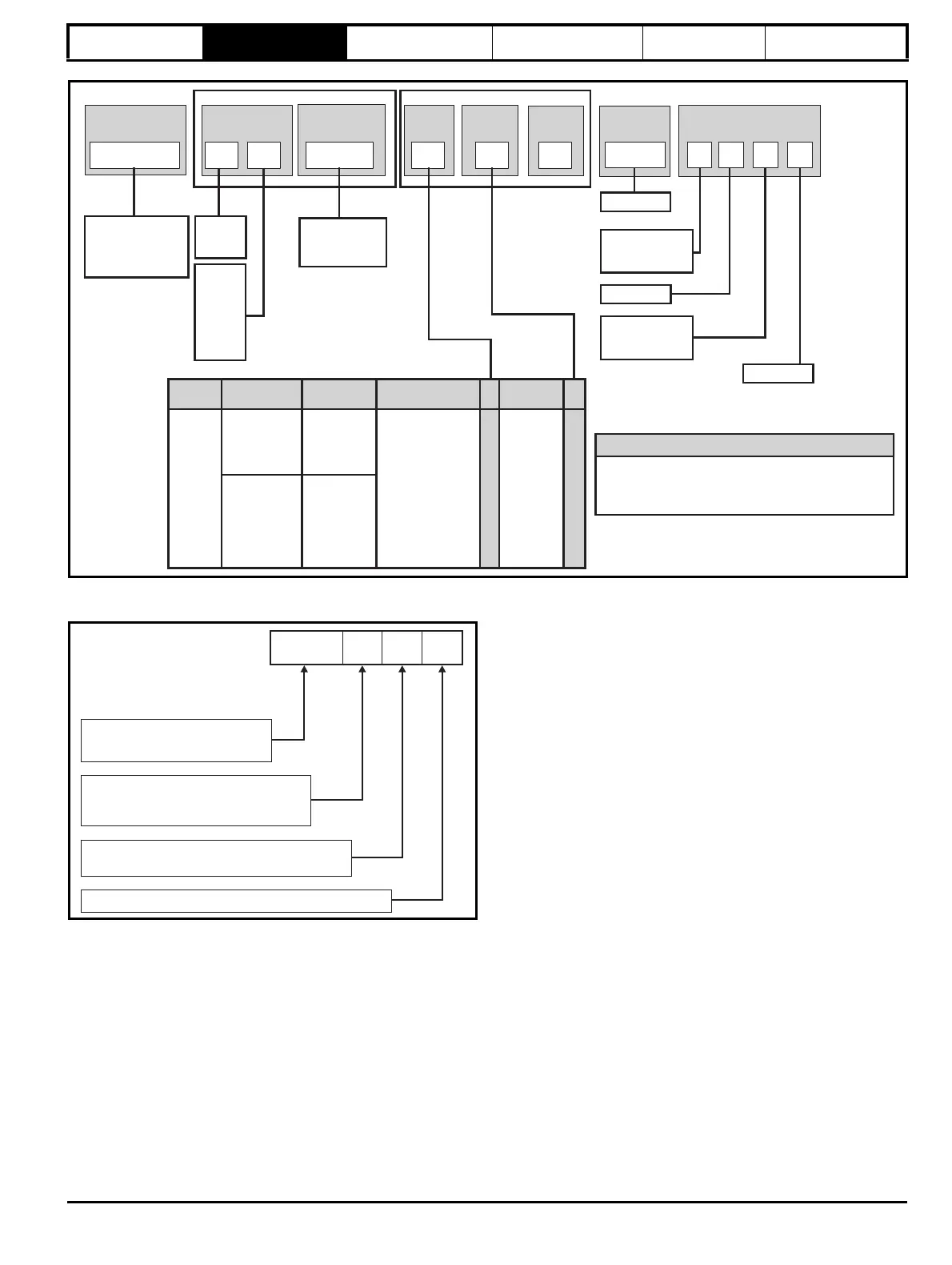
Figure 2-9 Drives model number
Figure 2-10 Input line reactor / output sharing choke
Unidrive Range:
M600-
M700-
M800-
Range &
Derivative
Power
Mxxx-
03
4
00078
Control
1
Electrical Specification Drive Format
Frame & Volts
Frames
Power
Description
Power Format
14
15
Control
Unasigned
Range ID
Frame
size
Current rating:
Heavy duty
rating x 10
Voltage
rating:
2=200 V
4=400 V
5=575 V
6=690 V
Current
A
100A
B
1
000
Reserved
Reserved
Reserved
Conformal
coating:
0 = Standard
Brake Transistor:
B = Brake
N=No
Optional Build
09 to 11
AC to AC
DC to AC
External choke
(order separately)
6P rectifier plus
inverter
12P Rectifier plus
inverter
18P Rectifier plus
inverter
Inverter
Single drives
Mxxx-
Modular drives
M000-
(Unassigned
power stage
with no control
fitted)
E1
T
U
Standard
M000-FOLLOWER011100A0100
Mxxx-MASTER00011100A0100
Mxxx- STANDARD011100A0100
Control Module Range for Unassigned Modular Drives
NMMaster
DFFollower
INL:
Current rating step
OTL: Output sharing choke
INL
4 0 1
Input line reactor
0: Single
Voltage rating
4: 380V to 480V
6: 500V to 690V