Safety information Introduction Product information System configuration
Mechanical
Installation
Electrical Installation
20 Unidrive M Modular Installation Guide
Issue Number: 2
4 System configuration
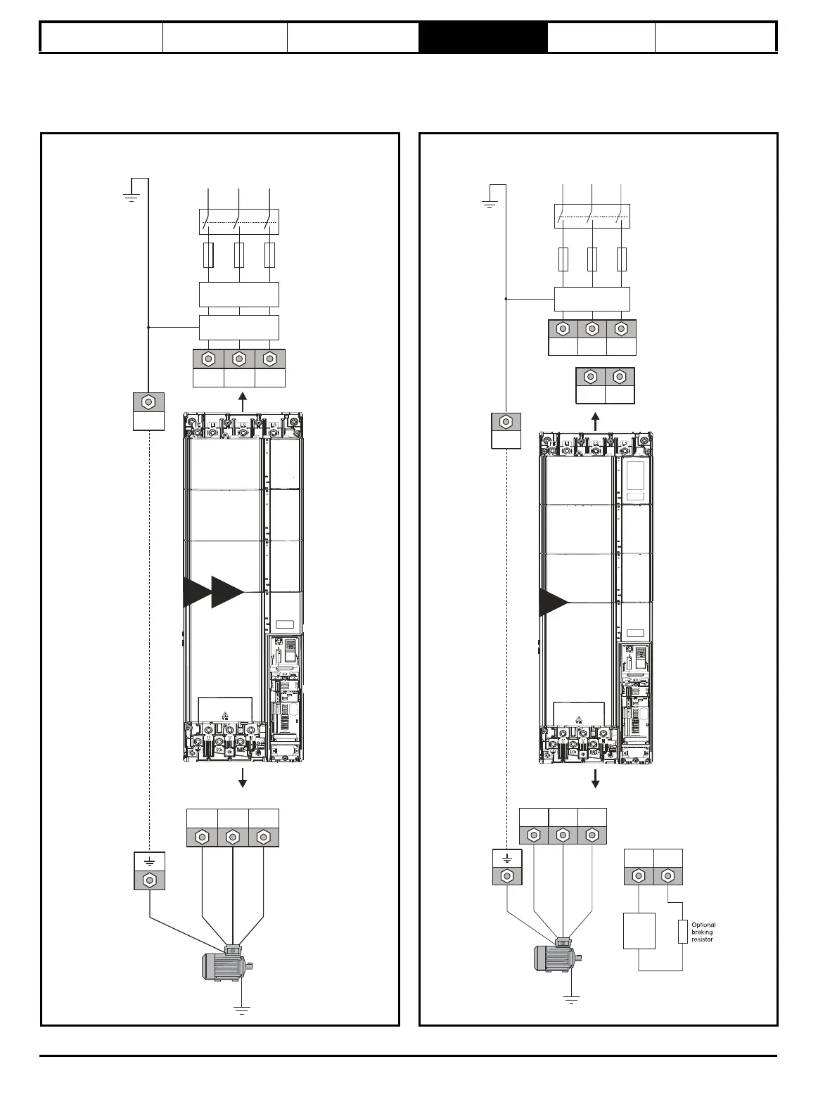
This chapter describes various Unidrive M size 9E,10E and 9A system configurations.
Figure 4-1 Layout for a size 9E or 10E module operating on a 3-
phase AC supply
Figure 4-2 Layout for a size 9A module operating on a 3-phase AC
supply
Input connections
Mains
Supply
L1 L2
Line reactor
Optional
EMC filter
Fuses
L3
L1 L2 L3
PE
Supply
ground
9E
10E
UVW
Motor
Optional ground
connection
Output connections
Input connections
Mains
Supply
L1 L2
Optional
EMC filter
Fuses
L3
L1 L2 L3
PE
Supply
ground
UVW
Motor
Optional ground
connection
+DC BR
Thermal
overload
protection
device
Output connections
9A
+DC -DC
*
*