Safety information Introduction Product information System configuration
Mechanical
Installation
Electrical Installation
Unidrive M Modular Installation Guide 47
Issue Number: 2
Figure 5-30 Pressure drop
Best practice: Size the enclosure air inlet and exit vents at least as
large as the venturi opening of the fan used. This will ensure a negligible
back pressure.
With 52.5 % open area: Pressure drop = 34
Selecting fan
Considerations when selecting fan:
• Dimensions and space limitation
• Required flow rate
• Static pressure
•Noise level
• Power supply
Table 5-5 Type of fan
Fan curves
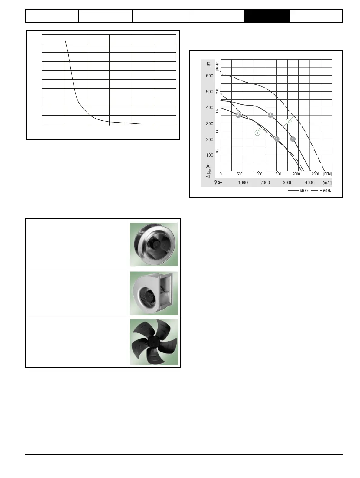
Once the type of fan has been selected the next step is to match the
system characteristics of your enclosure to the fan performance curve.
System operating point is:
Static pressure = 34 Pa
Flow rate= 4212.5 m
3
/hr
Selected fan is a Backward curved centrifugal blower to place in the roof
and take advantage of the perpendicular flow and high flow rate
properties.
Figure 5-31 AC supply 400 mm diameter blower performance
Final summary
1. Enclosure fans can be placed on inlet and outlet depending on
system limitations.
2. Considerations with fan on outlet:
• Higher Ambient temperature surrounding fan, can affect fan life.
• Depressurisation of enclosure which may draw in dust through
any apertures.
3. Considerations with fan on inlet:
• Proximity of dust filter to fan, can create excess back pressure
on fan
• Non-uniform flow across internal components
4. Dust filters:
Use the largest filter possible, in order to:
a. Increase dust capacity
b. Reduce pressure drop
5. Make sure Drive inlets are as close to the enclosure air inlet as
possible
6. Do not block the inlet and outlets of the drive airflow. Keep to best
practice spacing between drives and other parts in enclosure.
7. Beware of blocking air inlets or outlets with cable routing.
5.7 Heatsink fan operation
The Unidrive M size 9, 10 and Rectifier are ventilated by a heatsink
mounted fan and an auxiliary fan to ventilate the drive box. The fan
housing forms a baffle plate, channelling the air through the heatsink
chamber. Thus, regardless of mounting method (surface mounting or
through-panel mounting), the installation of additional baffle plates is not
required.
Ensure the minimum clearances around the drive are maintained to
allow air to flow freely.
The heatsink fan on Unidrive M size 9, 10 and Rectifier is a variable
speed device. The drive controls the speed at which the fan runs based
on the temperature of the heatsink and the drive's thermal model
system. The Unidrive M size 9 and 10 are also installed with variable
speed fans to ventilate the capacitor bank.
Backward curved Blower (Centrifugal)
• Outward flow perpendicular to inward flow
• Good at high + low back pressures
• Good resistance to dust and dirt due to
impeller design
• Do not need cowling
• Relatively small diameters required for
high airflow
Forward curved blower (Centrifugal)
• Requires cowling
• Good at directing flow
Axial Fan
• Not good at high pressure but good for
low pressure applications such as room
venting and ducting
• Inward flow and outward flow is in same
direction
• Good in straight line duct applications.
• Large diameters required for high air flows
250
200
150
100
50
0
Pressure drop (Pa)
0 20406080
Total open area (%)
100
400
350
300
500
450
80