Safety information Introduction Product information System configuration
Mechanical
Installation
Electrical Installation
Unidrive M Modular Installation Guide 75
Issue Number: 2
Figure 6-26 Surge suppression for digital and unipolar inputs and
outputs
Figure 6-27 Surge suppression for analog and bipolar inputs and
outputs
Surge suppression devices are available as rail-mounting modules, e.g.
from Phoenix Contact:
Unipolar TT-UKK5-D/24 DC
Bipolar TT-UKK5-D/24 AC
These devices are not suitable for encoder signals or fast digital data
networks because the capacitance of the diodes adversely affects the
signal. Most encoders have galvanic isolation of the signal circuit from
the motor frame, in which case no precautions are required. For data
networks, follow the specific recommendations for the particular
network.
6.11 Communications connections
The Unidrive M700 / M702 drive offers Ethernet fieldbus
communications and the Unidrive M701 drive offers a 2 wire 485
interface. This enables the drive set-up, operation and monitoring to be
carried out with a PC or controller if required.
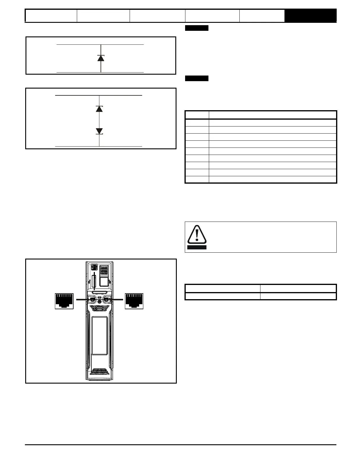
Figure 6-28 Location of the comms connectors
6.11.1 Unidrive M700 / M702 Ethernet fieldbus
communications
The Ethernet option provides two RJ45 connections with an Ethernet
switch for easy network creation.
Standard UTP (unshielded twisted pair) or STP (shielded twisted pair)
cables are supported. It is recommended that a minimum specification
CAT5e is used in new installations. As the drive supports the ‘Auto
cross-over detection’ a cross-over cable is not required.
The shell of the RJ45 connector is isolated from the 0 V of the drive
control terminals but it is connected to ground.
6.11.2 Unidrive M701 485 serial communications
The 485 option provides two parallel RJ45 connectors allowing easy
daisy chaining. The drive only supports Modbus RTU protocol. See
Table 6-20 for the connection details.
Standard Ethernet cables are not recommended for use when
connecting drives on a 485 network as they do not have the correct
twisted pairs for the pinout of the serial comms port.
Table 6-20 Serial communication port pin-outs
Minimum number of connections are 2, 3, 7 and shield.
6.11.3 Unidrive M701 Isolation of the 485 serial
communications port
The serial PC communications port is double insulated and meets the
requirements for SELV in EN 50178:1998.
An isolated serial communications lead has been designed to connect
the drive to IT equipment (such as laptop computers), and is available
from the supplier of the drive. See below for details:
Table 6-21 Isolated serial comms lead details
The “isolated serial communications” lead has reinforced insulation as
defined in IEC60950 for altitudes up to 3,000 m.
Signal from plant Signal to drive
0V 0V
30V zener diode
e.g. 2xBZW50-15
Signal from plant Signal to drive
0V 0V
2 x 15V zener diode
e.g. 2xBZW50-15
Pin Function
1 120 Ω Termination resistor
2RX TX
3 Isolated 0 V
4 +24 V (100 mA)
5 Isolated 0 V
6 TX enable
7RX\ TX\
8 RX\ TX\ (if termination resistors are required, link to pin 1)
Shell Isolated 0 V
In order to meet the requirements for SELV in IEC60950 (IT
equipment) it is necessary for the control computer to be
grounded. Alternatively, when a laptop or similar device is
used which has no provision for grounding, an isolation
device must be incorporated in the communications lead.
Part number Description
4500-0096 CT USB Comms cable