Safety information Introduction Product information System configuration
Mechanical
Installation
Electrical Installation
62 Unidrive M Modular Installation Guide
Issue Number: 2
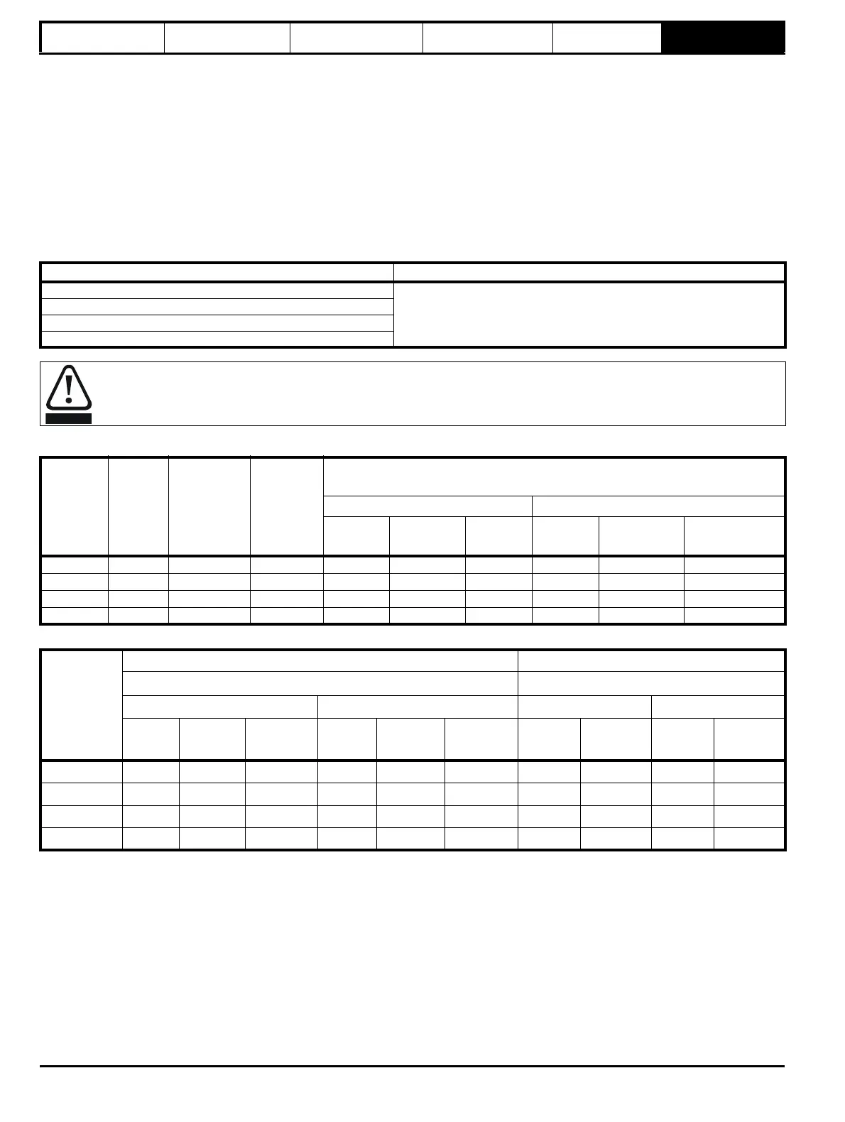
6.6 Ratings
The input current is affected by the supply voltage and impedance.
Typical input current
The values of typical input current are given to aid calculations for power flow and power loss.
The values of typical input current are stated for a balanced supply.
Maximum continuous input current
The values of maximum continuous input current are given to aid the selection of cables and fuses. These values are stated for the worst case
condition with the unusual combination of stiff supply with bad balance. The value stated for the maximum continuous input current would only be
seen in one of the input phases. The current in the other two phases would be significantly lower.
The values of maximum input current are stated for a supply with a 2 % negative phase-sequence imbalance and rated at the supply fault current
given in Table 6-9.
Table 6-9 Supply fault current used to calculate maximum input currents
Table 6-10 Size 10 AC Rectifier current and fuse ratings
Table 6-11 Cable ratings for size 10 Rectifier
Model Symmetrical fault level (kA)
9A
100
9E / 10E
9D / 10D
Rectifier
Fuses
The AC supply to the drive must be installed with suitable protection against overload and short-circuits. Table 6-10 shows
recommended fuse ratings. Failure to observe this requirement will cause risk of fire.
Model
Typical
input
current
Maximum
continuous
input current
Maximum
overload
input
current
Fuse rating
IEC UL/USA
Nominal Maximum
Class
Nominal Maximum
Class
AA A
AA A A
10204100 333 361 494 450 450 gR 450 450 HSJ
10404520 370 396 523 450 450 gR 450 450 HSJ
10502430 202 225 313 250 250 gR 250 250 HSJ
10602480 202 225 313 250 250 gR 250 250 HSJ
Model
Cable size (IEC) Cable size (UL)
mm
2
AWG or kcmil
Input Output Input Output
Nominal Maximum
Installation
method
Nominal Maximum
Installation
method
Nominal Maximum Nominal Maximum
10204100 2 x 150 2 x 150 C 2 x 120 2 x 120 C 2 x 300 2 x 300 2 x 400 2 x 400
10404520 2 x 150 2 x 150 C 2 x 150 2 x 150 C 2 x 350 2 x 350 2 x 500 2 x 500
10502430 2 x 95 2 x 95 B2 2 x 95 2 x 95 B2 2 x 3/0 2 x 3/0 2 x 3/0 2 x 3/0
10602480 2 x 95 2 x 95 B2 2 x 95 2 x 95 B2 2 x 3/0 2 x 3/0 2 x 3/0 2 x 3/0