Safety information Introduction Product information System configuration
Mechanical
Installation
Electrical Installation
8 Unidrive M Modular Installation Guide
Issue Number: 2
2 Introduction
The Unidrive M drive offers the possibility of implementing many custom
power systems with a wide range of power modules. The power range is
110 kW to 3.8 MW and the modular design of input and output stages
enables a wide range of very compact and efficient systems to be
realized. These include:
• Parallel output stages for higher power motors:
Up to a maximum of 20 modules
(1 master module with up to 19 follower modules, OR
1 remote mounted control master pod controlling up to 20
followers. This allows the user to place all circuitry in one low
voltage cabinet)
• Common DC bus multi-drive systems for:
Connection to larger existing power supplies
Energy sharing between motoring and regenerating drives
• Active front end drive systems for:
Minimizing supply current harmonics
Four quadrant motor control
• Multiple controlled rectifier bridges for:
Minimizing supply current harmonics by drawing 6, 12 or 18
pulse supply load currents.
2.1 Rectifier
The Unidrive M Rectifier is a half controlled SCR/thyristor bridge and is
used as a front end to the size 9 or size 10 Inverter module. The Rectifier
cannot be used as a stand alone Rectifier for several smaller drives.
Figure 2-1 Half controlled SCR/thyristor
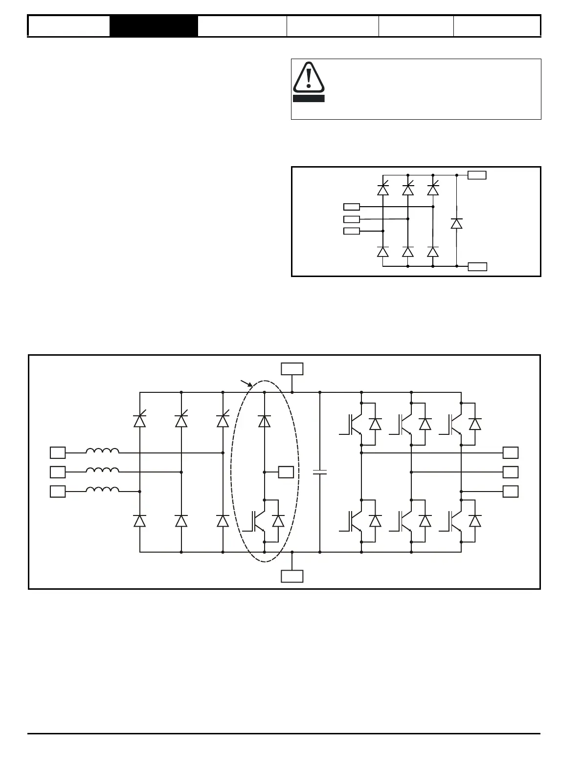
2.2 Size 9A drives
The size 9A is a complete drive with internal rectifier and AC input line chokes (AC in to AC out). It can provide a maximum continuous output current
of 266 A (400 V drive). DC connections are available for use in regen and bus-parallel applications. The size 9A is available with or without a braking
IGBT installed.
Figure 2-2 Size 9A Inverter schematic
A separate input line reactor (INLXXX) of at least the value
shown in Table 6-2 400 V input line reactor ratings on page 59
and Table 6-3 690 V input line reactor ratings on page 59
must be used with the rectifiers. Failure to provide sufficient
reactance could damage or reduce the service life of the
rectifier or inverter.