Safety information Introduction Product information System configuration
Mechanical
Installation
Electrical Installation
Unidrive M Modular Installation Guide 9
Issue Number: 2
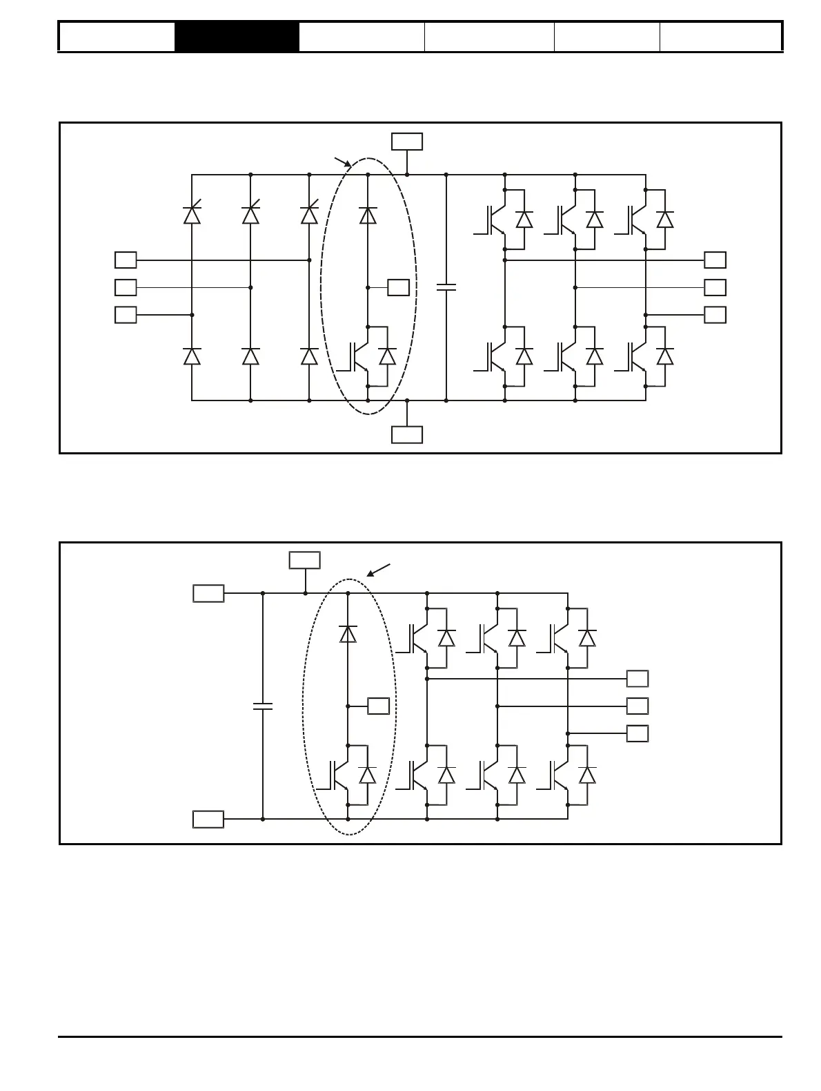
2.3 Size 9E and 10E drives
The size 9E and 10E is a complete drive with internal rectifier (AC in to AC out). It can provide a maximum continuous output current of 361 A (400 V
drive).
Figure 2-3 Size 9E and Inverter schematic
2.4 Size 9D and 10D Inverter
The size 9D and 10D is an inverter stage only (DC in to AC out). If a rectifier is required, then an AC input line reactor must also be installed. It can
provide a maximum continuous output current of 361 A (400 V drive). DC connections can be used for regen and bus-parallel applications. The size
9D and 10D is available with or without a braking IGBT installed.
Figure 2-4 Size 9D and 10D Inverter schematic