Safety information Introduction Product information System configuration
Mechanical
Installation
Electrical Installation
30 Unidrive M Modular Installation Guide
Issue Number: 2
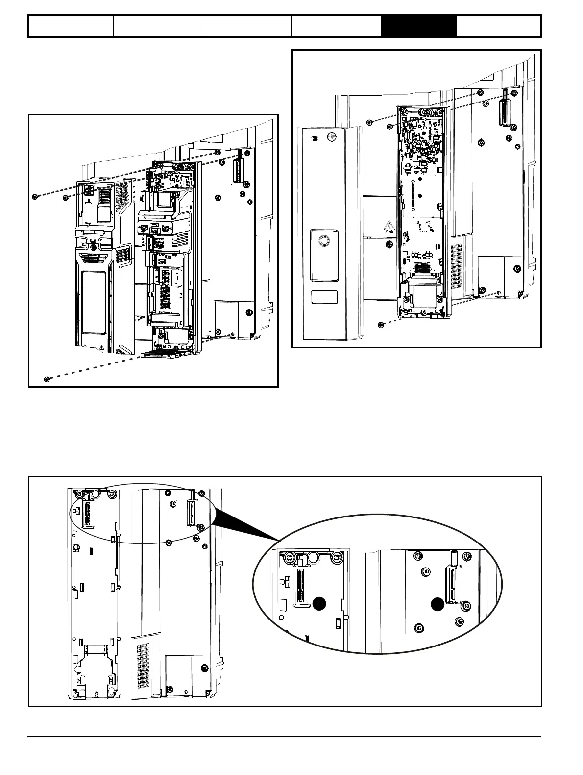
5.4 Mounting of the control master/
follower/standard pod
For control master/follower pod paralleling connections, refer to Figure
5-10 Parallel control connections on page 31.
Figure 5-7 Mounting the control master or standard pod on the
drive
1. In order to expose the top mounting hole, the terminal covers need
to be removed. This is done by undoing the terminal cover screw
highlighted and then removing the two plastic covers.
2. Care must be taken when installing master control pod. Refer to
Figure 5-9. Use the 2 x M6 screws to mount the control master pod
to the drive in the position shown.
3. The terminal covers can then be re-installed.
Figure 5-8 Mounting the control follower pod on the drive
1. In order to expose the mounting holes, remove the control follower
pod cover. This is done by undoing the screws highlighted and
pulling the cover off.
2. Care must be taken when installing control follower pod. Refer to
Figure 5-9. Use the 2 x M6 screws to mount the control follower pod
to the drive in the position shown.
3. The cover can then be re-installed.
Figure 5-9 Control master/follower pod and power module base plate connectors