Safety information Introduction Product information System configuration
Mechanical
Installation
Electrical Installation
Unidrive M Modular Installation Guide 29
Issue Number: 2
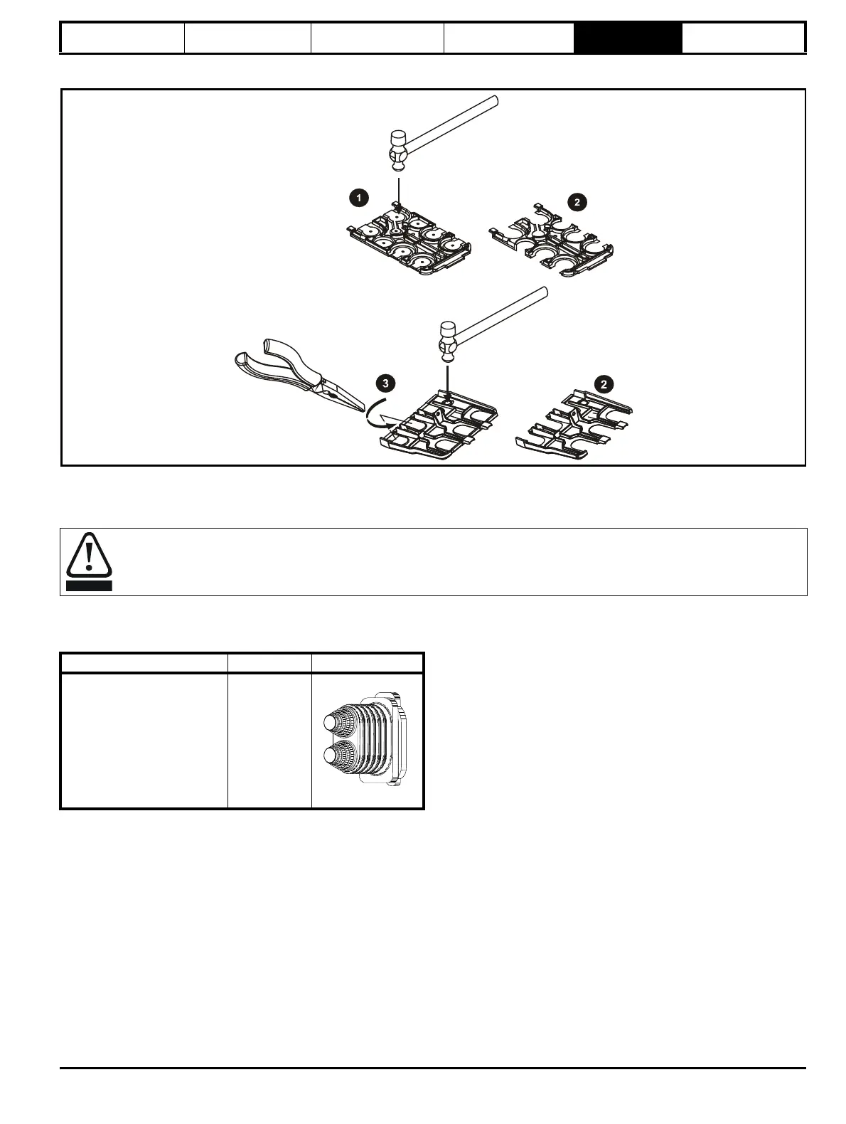
5.3.2 Removing the finger-guard and DC terminal cover break-outs
Figure 5-6 Removing the finger-guard break-outs
All sizes:
Place the finger-guard on a flat solid surface and hit relevant break-outs with hammer as shown (1). Pliers can be used to remove the breakouts,
grasp the relevant break-out with pliers and twist it as shown (3). Continue until all the required break-outs have been removed (2). Remove any flash
/ sharp edges once the break-outs have been removed.
Grommet kits are available for size 9 and 10 finger guards.
Table 5-1 Grommet kits
The grommets must be installed to ensure ingress protection to IP20 and to avoid the risk of fire in the event of a major internal failure.
Drive size Part number Picture
Size 9 and 10 - Kit of 8 x double
entry grommets
3470-0107-00