Safety information Introduction Product information System configuration
Mechanical
Installation
Electrical Installation
Unidrive M Modular Installation Guide 13
Issue Number: 2
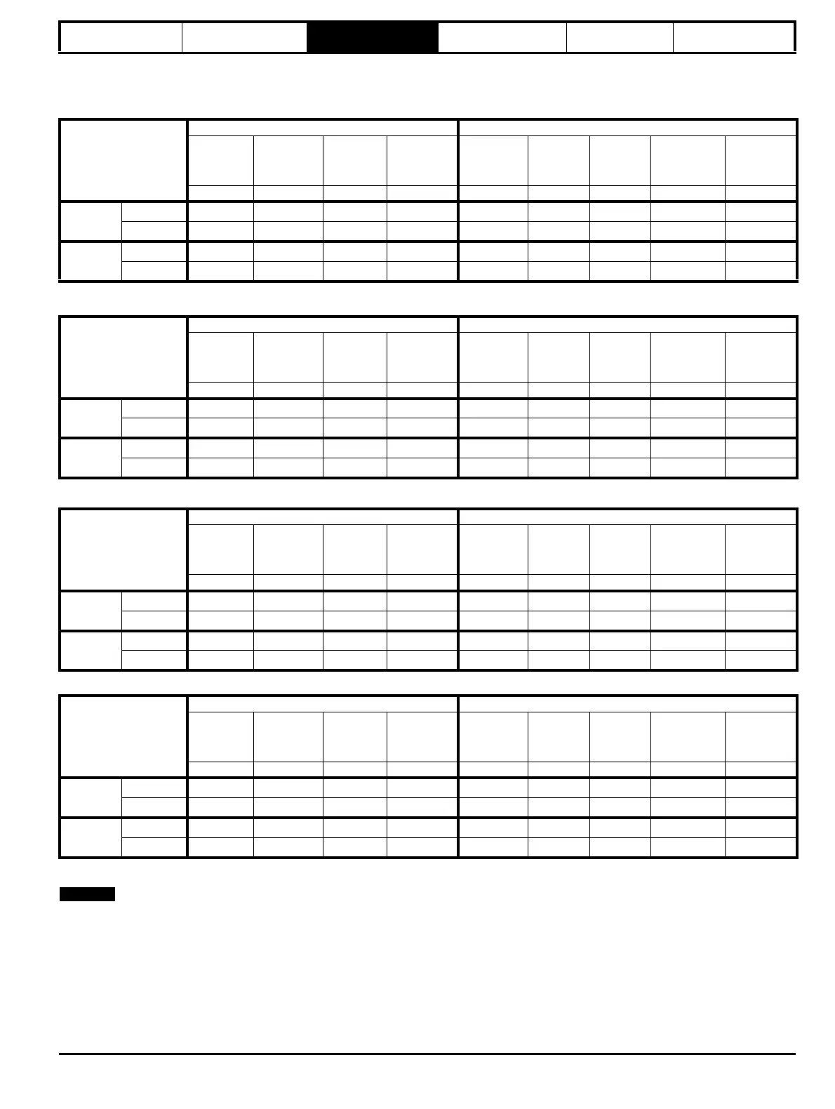
The continuous current ratings given are for maximum 40 °C (104 °F), 1000 m altitude and 3.0 kHz switching frequency. Derating is required for
higher switching frequencies, ambient temperature >40 °C (104 °F), high altitude and parallel applications. For further information, refer to section
6.6 Ratings .
Table 3-1 Size 9 and 10 200 V drive ratings (200 V to 240 V ±10 %)
Table 3-2 Size 9 and 10 400 V drive ratings (380 V to 480 V ±10 %)
Table 3-3 Size 9 and 10 575 V drive ratings (500 V to 575 V ±10 %)
Table 3-4 Size 9 and 10 690 V drive ratings (500 V to 690 V ±10 %)
5% derating should be applied when paralleling two or more inverters.
* These ratings are for 2 kHz switching frequency. For ratings at 3 kHz switching frequency, refer to the Drive User Guide.
Model
Normal Duty Heavy Duty
Maximum
continuous
output
current
Nominal
power at
230 V
Motor
power at
230 V
Peak
current
Maximum
continuous
output
current
Open loop
peak
current
RFC peak
current
Nominal
power at
230 V
Motor
power at
230 V
AkWhpA A AAkW hp
9D / 9E / 9A
09201760 216 55 75 237.6 176 264 308 45 60
09202190 266 75 100 292.6 219 328 383.25 55 75
10D / 10E
10202830 325 90 125 357.5 283 424.5 495.25 75 100
10203000 360 110 150 396 300 450 525 90 125
Model
Normal Duty Heavy Duty
Maximum
continuous
output
current
Nominal
power at
400 V
Motor
power at
460 V
Peak
current
Maximum
continuous
output
current
Open loop
peak
current
RFC peak
current
Nominal
power at
400 V
Motor
power at
460 V
AkWhpA A AAkW hp
9D / 9E / 9A
09402000 221 110 150 243.1 200* 300
350
90 150
09402240 266* 132 200 292.6 224* 336
392
110 150
10D / 10E
10402700 320 160 250 352 270 405
472.5
132 200
10403200 361 200 300 397.1 320* 480
560
160 250
Model
Normal Duty Heavy Duty
Maximum
continuous
output
current
Nominal
power at
575 V
Motor
power at
575 V
Peak
current
Maximum
continuous
output
current
Open loop
peak
current
RFC peak
current
Nominal
power at
575 V
Motor
power at
575 V
AkWhpA A AAkW hp
9D / 9E / 9A
09501040
125 110 125 137.5 104 156 182 75 100
09501310
150 110 150 165 131 196.5 229.25 90 125
10D / 10E
10501520
200 130 200 220 152 228 266 110 150
10501900
200 150 200 220 190 285 332.5 132 200
Model
Normal Duty Heavy Duty
Maximum
continuous
output
current
Nominal
power at
690 V
Motor
power at
690 V
Peak
current
Maximum
continuous
output
current
Open loop
peak
current
RFC peak
current
Nominal
power at
690 V
Motor
power at
690 V
AkWhpA A AAkW hp
9D / 9E / 9A
09601040
125 110 150 137.5 104 156 182 90 125
09601310
150 132 175 170.5 131 196.5 229.25 110 150
10D / 10E
10601500
172 160 200 189.2 150 225 262.5 132 175
10601780
197 185 250 216.7 178 261 311.5 160 200