Safety information Introduction Product information System configuration
Mechanical
Installation
Electrical Installation
Unidrive M Modular Installation Guide 15
Issue Number: 2
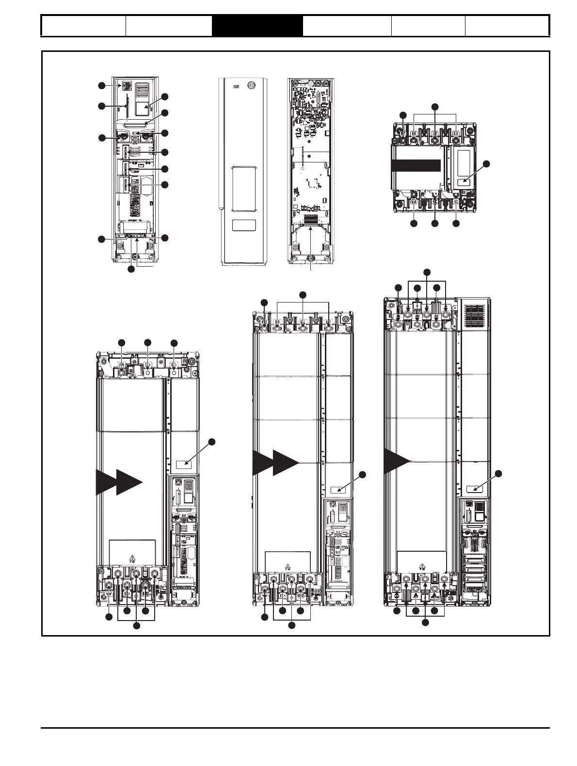
Figure 3-1 Features of the Unidrive M
Master Pod
Output to follower
1
2
3
4
5
6
Follower Pod
Input from Master /
Output to follower
Cover
Base
7
8
9
10
11
12
9E
10E
2
13
14
14
15
18
17
9D
10D
2
15
14
16
17
15
18
14
14 15 16
14
13
2
Rectifier
15
19
15
13
14
19
15
19
13
19
16
14 15
18
17
9A
2
2
Key
1. Rating label 6. Option module slot 3 11. NV media card slot 16. DC bus -
2. Identification label 7. Relay connections 12. Keypad connection 17. Motor connections
3. Status LED 8. Position feedback connections 13. AC supply connections 18. Braking terminal
4. Option module slot 1 9. Control connections 14. Ground connections
5. Option module slot 2 10. Communications port 15. DC bus +