EasyManuals Logo

Nidec Control Techniques M701 User Manual

Nidec Control Techniques M701
92 pages
To Next Page IconTo Next Page
To Previous Page IconTo Previous Page
Page #24 background imageLoading...
Page #24 background image
Safety information Introduction Product information System configuration
Mechanical
Installation
Electrical Installation
24 Unidrive M Modular Installation Guide
Issue Number: 2
Figure 4-6 Layout for two or more Unidrive M 9D or 10D modules operating on a 3-phase AC supply
L3
L2
L1
Master Follower
INLXXX
Line reactor
INLXXX
Line reactor
+DC +DC-DC -DC
CommsComms
24 V24 V
0V0V
FusesFuses
OTLXXX
sharing
chokes
UVW UVW
OTLXXX
sharing
Parallelling cable
chokes
9D 10D 9D 10D
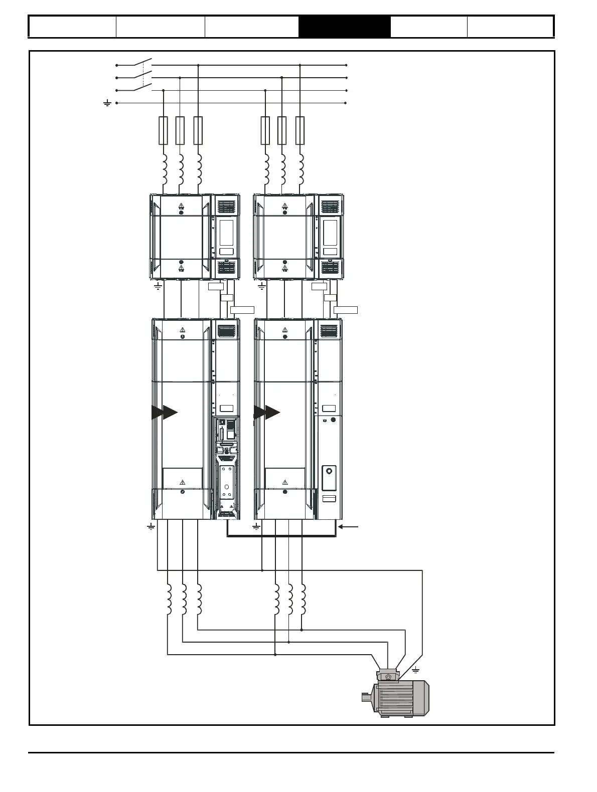
Current sharing between drives
whose motor outputs are
connected in parallel
When used from a 3 phase supply, it is
preferable not to link the DC bus
because the impedance between DC
and each inverter output is just the
impedance of the output chokes. Also,
on the input side, input current sharing
is determined only by making the
temperature of the two rectifiers similar
and by ensuring that both rectifiers see
the same impedance to the line power
supply.

Questions and Answers:

Question and Answer IconNeed help?

Do you have a question about the Nidec Control Techniques M701 and is the answer not in the manual?

Nidec Control Techniques M701 Specifications

General IconGeneral
BrandNidec
ModelControl Techniques M701
CategoryDC Drives
LanguageEnglish

Related product manuals