Safety information Introduction Product information System configuration
Mechanical
Installation
Electrical Installation
Unidrive M Modular Installation Guide 57
Issue Number: 2
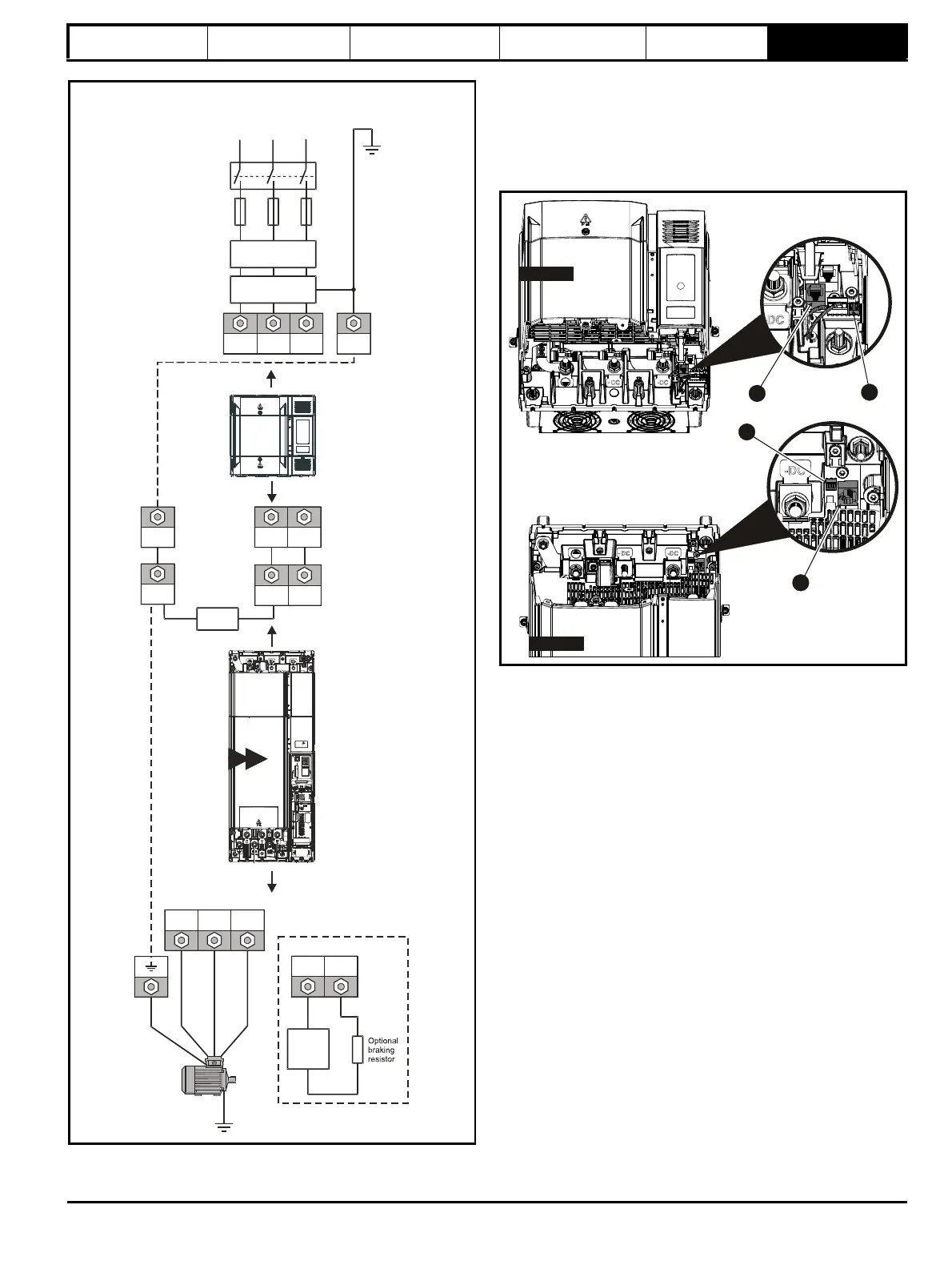
Figure 6-3 Unidrive M size 9D/10D power connections
* See section 6.1.3 Ground connections .
6.1.2 Connecting the RJ45 communication cable
and 24 V supply cable between Inverter and
Rectifier
An RJ45 patch cable and a 24 V supply cable must be connected
between the rectifier and the inverter. The RJ45 cable carries control
signal and start-up command signal from the inverter to the rectifier.
Figure 6-4 Locations of the connections for the connecting cables
1. RJ45 connection.
2. 24 Vdc supply connection.
UVW
Motor
Optional ground
connection
+DC BR
Thermal
overload
protection
device
Output connections
Input connections
Mains
Supply
L1 L2
Line reactor
(INLXXX)
Optional
EMC filter
Fuses
L3
L1 L2 L3
Supply
Rectifier
ground
*
+DC -DC
Internal
EMC filter
*
PE
+DC -DCPE
PE
Optional
9D 10D