Safety information Introduction Product information System configuration
Mechanical
Installation
Electrical Installation
Unidrive M Modular Installation Guide 73
Issue Number: 2
6.10.5 Ensure good EMC grounding.
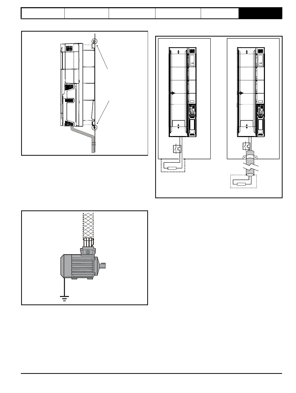
Figure 6-20 Grounding the drive, motor cable shield and filter
Connect the shield of the motor cable to the ground terminal of the motor
frame using a link that is as short as possible and not exceeding 50 mm
(2 in) long. A full 360
°
termination of the shield to the terminal housing of
the motor is beneficial.
It is unimportant for EMC purposes whether the motor cable contains an
internal (safety) ground core, or there is a separate external ground
conductor, or grounding is through the shield alone. An internal ground
core will carry a high noise current and therefore it must be terminated
as close as possible to the shield termination.
Figure 6-21 Grounding the motor cable shield
Unshielded wiring to the optional braking resistor(s) may be used,
provided the wiring does not run external to the enclosure. Ensure a
minimum spacing of 300 mm (12 in) from signal wiring and the AC
supply wiring to the external EMC filter. Otherwise this wiring must be
shielded.
Figure 6-22 Shielding requirements of optional external braking
resistor
If the control wiring is to leave the enclosure, it must be shielded and the
shield(s) clamped to the drive using the grounding bracket as shown in
Figure 6-23. Remove the outer insulating cover of the cable to ensure
the shield(s) make contact with the bracket, but keep the shield(s) intact
until as close as possible to the terminals
Alternatively, wiring may be passed through a ferrite ring, part no. 3225-
1004.
Motor cable screen
(unbroken) physically
fixed to the backplate.
Ensure direct
metal contact
at drive and
filter (not shown)
mounting
points (any
paint must be
removed).
braking resistor
Enclosure
+DC BR
braking resistor
Enclosure