Safety information Introduction Product information System configuration
Mechanical
Installation
Electrical Installation
Unidrive M Modular Installation Guide 77
Issue Number: 2
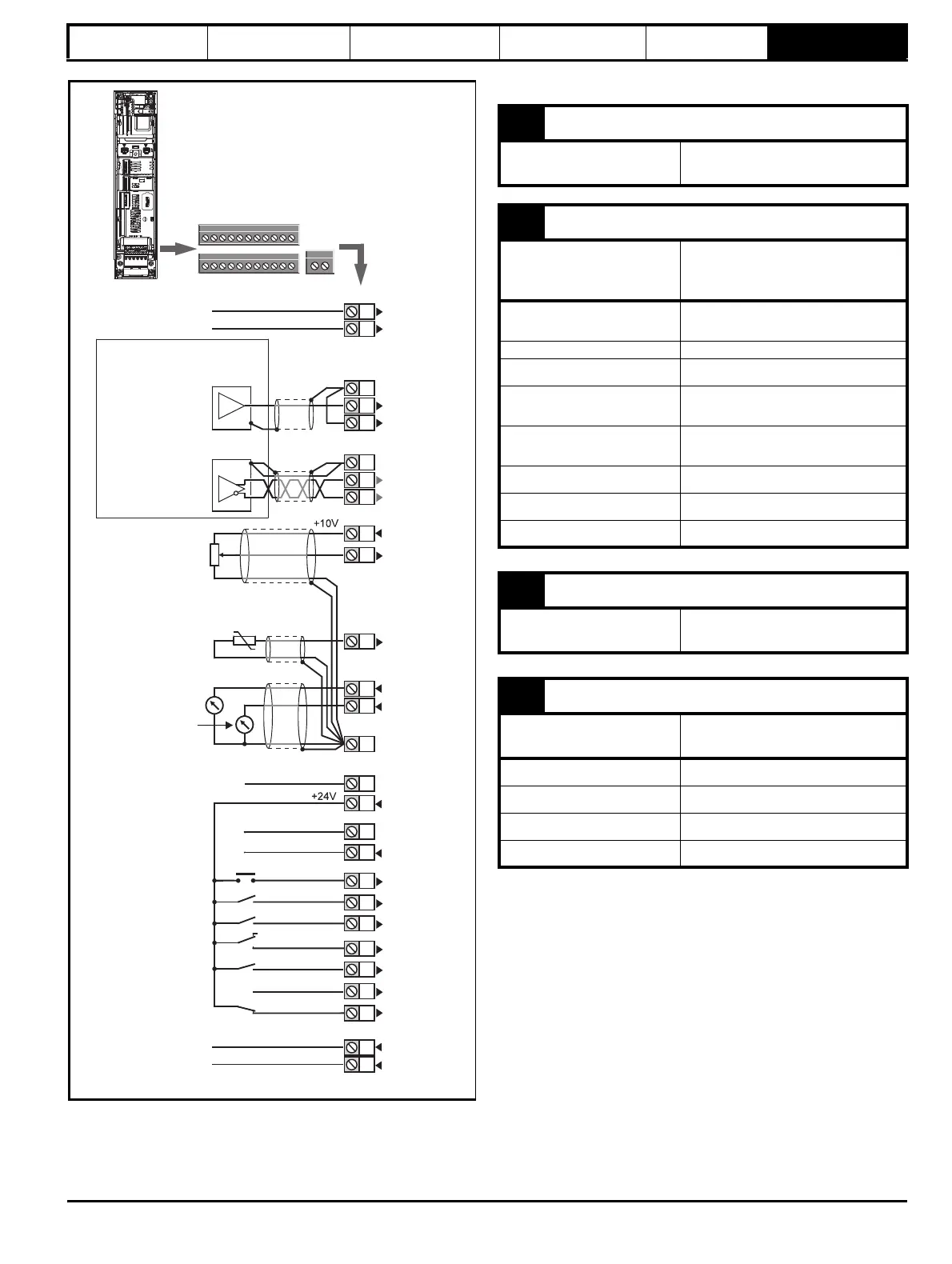
Figure 6-29 Default terminal functions
*The SAFE TORQUE OFF / Drive enable terminal is a positive logic input
only.
6.12.2 Unidrive M600 / M700 / M701 control terminal
specification
1
11
Polarized
connectors
21 31
41
42
0V common
External 24V supply
0V common
Analog frequency/speed
reference 1
Connections for
single-ended input
signal
Connections for
differential input signal
0V common
0V common
0V common
Analog input 2
Analog input 1
0V common
1
2
5
6
3
5
6
3
21
22
23
24
25
26
27
28
29
30
31
41
42
At zero speed
Reset
Run forward
Run reverse
Analog input 1/
input 2 select
Jog forward select
SAFE TORQUE OFF /
Drive enable*
Relay
(Over voltage
category II)
Drive OK
Speed / frequency
0V common
Analog
frequency/speed
reference 2
4
7
11
9
10
8
Torque (active
current)
Analog input 3
Motor thermistor
1 0V common
Function
Common connection for all
external devices
2 +24V external input
Function
To supply the control circuit
without providing a supply to the
power stage
Programmability
Can be used as digital input when using
an external 24 V supply
Sample / update 2 ms
Nominal voltage +24.0 Vdc
Minimum continuous operating
voltage
+19.2 Vdc
Maximum continuous operating
voltage
+28.0 Vdc
Minimum start-up voltage 21.6 Vdc
Recommended power supply 40 W 24 Vdc nominal
Recommended fuse 3 A, 50 Vdc
3 0V common
Function
Common connection for all
external devices
4 +10V user output
Function
Supply for external analog
devices
Voltage 10.2 V nominal
Voltage tolerance ±1 %
Nominal output current 10 mA
Protection Current limit and trip @ 30 mA