Safety information Introduction Product information System configuration
Mechanical
Installation
Electrical Installation
Unidrive M Modular Installation Guide 79
Issue Number: 2
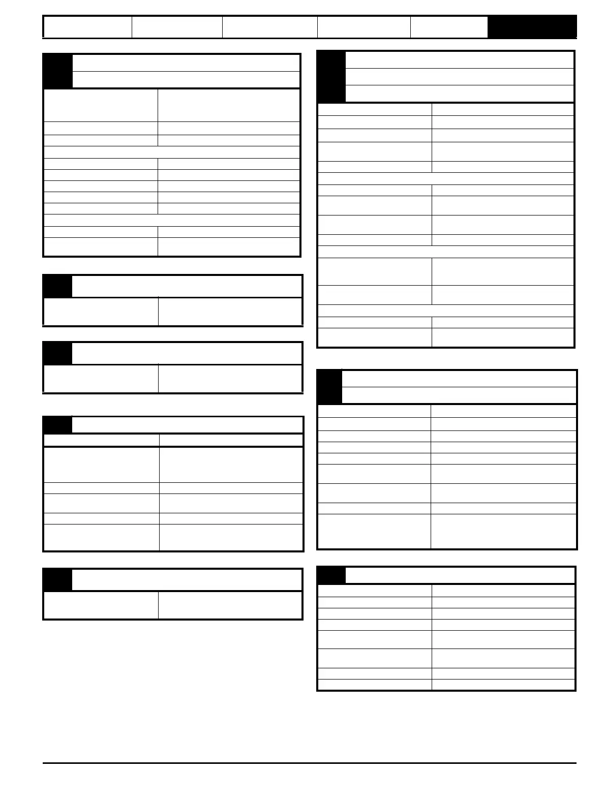
9 Analog output 1
10 Analog output 2
Terminal 9 default function
OL> Motor FREQUENCY output
signal
RFC> SPEED output signal
Terminal 10 default function Motor active current
Type of output Bipolar single-ended analog voltage
Operating in Voltage mode (default)
Voltage range ±10 V ±5 %
Maximum offset ±120 mV
Maximum output current ±20 mA
Load resistance ≥1 k Ω
Protection 20 mA max. Short circuit protection
Common to all modes
Resolution 10-bit
Sample / update period
250 µs (output will only change at update
the rate of the source parameter if slower)
11 0V common
Function
Common connection for all
external devices
21 0V common
Function
Common connection for all
external devices
22
+24 V user output (selectable)
Terminal 22 default function +24 V user output
Programmability
Can be switched on or off to act as a fourth
digital output (positive logic only) by setting
the source Pr 08.028 and source invert
Pr 08.018
Nominal output current 100 mA combined with DIO3
Maximum output current
100 mA
200 mA (total including all Digital I/O)
Protection Current limit and trip
Sample / update period
2 ms when configured as an output (output
will only change at the update rate of the
source parameter if slower)
23 0V common
Function
Common connection for all
external devices
24 Digital I/O 1
25 Digital I/O 2
26
Digital I/O 3
Terminal 24 default function AT ZERO SPEED output
Terminal 25 default function DRIVE RESET input
Terminal 26 default function RUN FORWARD input
Type
Positive or negative logic digital inputs,
positive logic voltage source outputs
Input / output mode controlled by... Pr 08.031, Pr 08.032 and Pr 08.033
Operating as an input
Logic mode controlled by... Pr 08.029
Absolute maximum applied
voltage range
-3 V to +30 V
Impedance
>2 mA @15 V from IEC 61131-2, type 1,
6.6 k Ω
Input thresholds 10 V ±0.8 V from IEC 61131-2, type 1
Operating as an output
Nominal maximum output current
100 mA (DIO1 & 2 combined)
100 mA (DIO3 & 24 V User Output
Combined)
Maximum output current
100 mA
200 mA (total including all Digital I/O)
Common to all modes
Voltage range 0 V to +24 V
Sample / Update period
2 ms (output will only change at the
update rate of the source parameter)
27
Digital Input 4
28 Digital Input 5
Terminal 27 default function
RUN REVERSE input
Terminal 28 default function
Analog INPUT 1 / INPUT 2 select
Type Negative or positive logic digital inputs
Logic mode controlled by... Pr 08.029
Voltage range 0 V to +24 V
Absolute maximum applied
voltage range
-3 V to +30 V
Impedance
>2 mA @15 V from IEC 61131-2, type 1,
6.6 k Ω
Input thresholds 10 V ±0.8 V from IEC 61131-2, type 1
Sample / Update period
250 µs when configured as an input with
destinations Pr 06.035 or Pr 06.036. 600 µs
when configured as an input with destination
Pr 06.029. 2 ms in all other cases.
29 Digital Input 6
Terminal 29 default function JOG SELECT input
Type Negative or positive logic digital inputs
Logic mode controlled by... Pr 08.029
Voltage range 0 V to +24 V
Absolute maximum applied
voltage range
-3 V to +30 V
Impedance
>2 mA @15 V from IEC 61131-2,
type 1,
6.6 k Ω
Input thresholds 10 V ±0.8 V from IEC 61131-2, type 1
Sample / Update period 2 ms