Safety information Introduction Product information System configuration
Mechanical
Installation
Electrical Installation
88 Unidrive M Modular Installation Guide
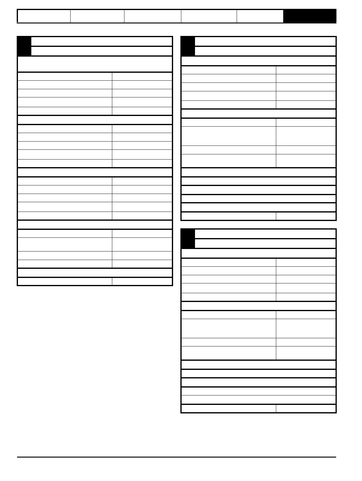
Issue Number: 2
5
Z, Data, Freeze, Ref H
6
Z\, Data\, Freeze\, Ref L
AB (0), FD (1), FR (2), AB Servo (3), FD Servo(4), FR Servo (5
),
SC SC (15)
Type EIA 485 differential receivers
Maximum input frequency 512 kHz
Line loading
Line termination components
120 Ω
(switchable)
Working common mode range –7 V to +12 V
SC Hiperface (7), SC EnDat (9), SC SSI (11), SC Servo (12)
Type EIA 485 differential receivers
Maximum input frequency 4 MHz
Line loading
Line termination components
120 Ω
(switchable)
Working common mode range –7 V to +12 V
EnDat (8), SSI (10), BiSS (13)
Type EIA 485 differential receivers
Maximum input frequency 4 MHz
Line loading
Line termination components
120 Ω
(switchable)
Working common mode range –7 V to +12 V
Resolver (14)
Type Differential voltage
Nominal voltage
0 – 2 Vrms depending on turns
ratio
Operating frequency 6 - 8 KHz
Line loading
Common to All
Absolute maximum applied voltage relative to 0V -9 V to 14 V
7
U, C, Not used, Not used
8
U\, C\, Not used, Not used
AB Servo (3), FD Servo(4), FR Servo (5
), SC Servo (12)
Type EIA 485 differential receivers
Maximum input frequency 512 kHz
Line loading
Line termination components
120 Ω
(switchable)
Working common mode range –7 V to +12 V
SC SC (15)
Type Differential voltage
Maximum Signal level
1.25 V peak to peak (sin with
regard to sinref and cos with
regard to cosref)
Maximum input frequency See Table
Maximum applied differential voltage and
common mode voltage range
±4 V
EnDat (8), SSI (10), BiSS (13)
Not used
Resolver (14)
Not used
Common to All
Absolute maximum applied voltage relative to 0V -9 V to 14 V
9
V, D, Not used, Not used
10
V\, D\, Not used, Not used
AB Servo (3), FD Servo(4), FR Servo (5
), SC Servo (12)
Type EIA 485 differential receivers
Maximum input frequency 512 kHz
Line loading
Line termination components
120 Ω
(switchable)
Working common mode range –7 V to +12 V
SC SC (15)
Type Differential voltage
Maximum Signal level
1.25 V peak to peak (sin with
regard to sinref and cos with
regard to cosref)
Maximum input frequency See Table
Maximum applied differential voltage and
common mode voltage range
±4 V
EnDat (8), SSI (10), BiSS (13)
Not used
Resolver (14)
Not used
Common to All
Absolute maximum applied voltage relative to 0V -9 V to 14 V